LiftMaster CAPAC Installation Manual - English French Spanish - Page 15
Access Control, Status, Auxiliary Relay, Primary Relay
 |
View all LiftMaster CAPAC manuals
Add to My Manuals
Save this manual to your list of manuals |
Page 15 highlights
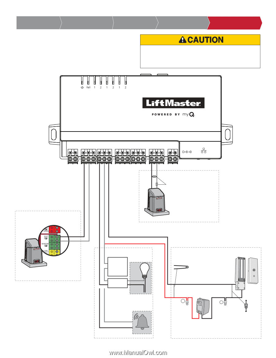
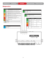
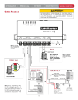
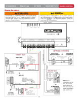
INTRODUCTION PRE-INSTALL Gate Access NETWORK MOUNTING/POWER ACCESS CONTROL PRE-INSTALL Not responsible for conflicts between the information listed in the wiring diagram and the requirements of your local building codes. The information is for suggested use ONLY. Check your local codes BEFORE installation. OUTPUT WIEGAND INPUT GATE 1 OUTPUT 2 SDA SCL NO COM NC NO COM NC 1 WIEGAND 2 D1 COM D0 D1 COM D0 INPUT POWER 1 GND 2 GND 12V-24V NORMALLY OPEN COMMON NORMALLY OPEN COMMON NORMALLY CLOSED NOTE: The SDA/SLA Gate input/output shall not be connected in UL applications. PRIMARY RELAY POWER ETHERNET STATUS EOL (End of Line) Resistor (1k ohm) GATE OPERATOR (connect to Aux Closed Limit switch refer to gate operator manual) NOTE: The application displays a warning if the gate does not open or close. EXIT GATE OPERATOR NOTE: For UL installations, only UL 325 Listed gate operators, UL 294 Listed electric door strikes or UL 294 Listed maglocks may be connected to relay output 1 or 2. AUXILIARY RELAY Low Voltage Power Supply Isolation Relay LIGHT LOAD LINE NEUTRAL OR OR ALARM BYPASS COMMON NORMALLY OPEN 15 *AUXILIARY RELAY MAGLOCK For AC Power: Install a Siemens S10K30MOV (Metal Oxide Varistor) (provided) or equivalent NORMALLY CLOSED Use 18-22 AWG COMMON - + Power for Maglock (Not Provided) DO NOT use the power supply for the controller For DC Power: Install a 1N4005 diode or equivalent
-
 1
1 -
2
-
3
-
4
-
5
-
6
-
7
-
8
-
9
-
 10
10 -
 11
11 -
 12
12 -
 13
13 -
 14
14 -
 15
15 -
 16
16 -
 17
17 -
 18
18 -
 19
19 -
 20
20 -
21
-
22
-
23
-
24
-
25
-
26
-
27
-
28
-
29
-
30
-
31
-
32
-
33
-
34
-
35
-
36
-
37
-
38
-
39
-
40
-
41
-
42
-
43
-
44
-
45
-
46
-
47
-
48
-
49
-
50
-
51
-
52
-
53
-
54
-
55
-
56
-
57
-
58
-
59
-
60
 |
 |