LiftMaster CSW24VDC CSW24VDC Installation Manual - Page 10
Installation, Important Safety Information, Step 1 Determine Location For Concrete Pad And Operator
 |
View all LiftMaster CSW24VDC manuals
Add to My Manuals
Save this manual to your list of manuals |
Page 10 highlights
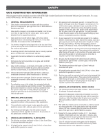
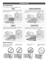
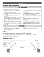
INSTALLATION IMPORTANT SAFETY INFORMATION To prevent SERIOUS INJURY or DEATH from a moving gate: • Pinch points must be guarded at ALL times. Install enclosed-style gate tracks and roller guards. • Place screen mesh 6 feet (1.8 m) high on the gate to prevent access through openings anywhere the gate may travel. • Mount controls at least 6 feet (1.8 m) from the gate or ANY moving part of the gate. • Install Warning signs on EACH side of gate in PLAIN VIEW. Permanently secure each Warning sign in a suitable manner using fastening holes. • This operator is intended for vehicular use ONLY. To prevent INJURY to pedestrians, a separate pedestrian access should be supplied, visible from the gate. Locate the pedestrian access where there is NOT a chance of INJURY at ANY point during full movement of the gate. • Contact sensors MUST be located at the leading and trailing edges, and post mounted BOTH inside and outside a horizontal swing gate. Non-contact sensors such as photoelectric sensors MUST be mounted across the gate opening and operate during BOTH the open and close cycles. • Entrapment protection devices MUST be installed to protect anyone who may come near a moving gate. • Locate entrapment protection devices to protect in BOTH the open and close gate cycles. • Locate entrapment protection devices to protect between moving gate and RIGID objects, such as posts or walls. • Too much force on gate will interfere with proper operation of safety reversal system. • NEVER increase force beyond minimum amount required to move gate. • NEVER use force adjustments to compensate for a binding or sticking gate. • If one control (force or travel limits) is adjusted, the other control may also need adjustment. • After ANY adjustments are made, the safety reversal system MUST be tested. Gate MUST reverse on contact with a rigid object. • DO NOT touch the heater when switch is on, heater may be hot. • To AVOID damaging gas, power or other underground utility lines, contact underground utility locating companies BEFORE digging more than 18 inches (46 cm) deep. STEP 1 • ALWAYS wear protective gloves and eye protection when changing the battery or working around the battery compartment. DETERMINE LOCATION FOR CONCRETE PAD AND OPERATOR For compact installation refer to the Appendix for installation steps 1-4, pages 43-44. DO NOT run the operator until instructed. The illustration below shows the recommended dimensions for a standard installation. If these dimensions are not applicable for your installation refer to the chart on the following page for alternate dimensions. STANDARD INSTALLATION Refer to the illustration to determine the measurements and location of the concrete pad. NOTE: There should only be a maximum of 4" (10.2 cm) from the center of the hinge to the edge of the post or column. If the distance is greater than 4" (10.2 cm) entrapment protection for this area is required. 4" (10.2 cm) maximum 25" 10" Outside Property Inside Property Hinge Center 46" 2" 35.5" 11" Long Arm 29.5" Short Arm 28" 24" Concrete Pad 9
-
 1
1 -
2
-
3
-
4
-
 5
5 -
 6
6 -
 7
7 -
 8
8 -
 9
9 -
 10
10 -
 11
11 -
 12
12 -
 13
13 -
 14
14 -
 15
15 -
16
-
17
-
18
-
19
-
20
-
21
-
22
-
23
-
24
-
25
-
26
-
27
-
28
-
29
-
30
-
31
-
32
-
33
-
34
-
35
-
36
-
37
-
38
-
39
-
40
-
41
-
42
-
43
-
44
-
45
-
46
-
47
-
48
-
49
-
50
-
51
-
52
-
53
-
54
-
55
-
56
 |
 |
