LiftMaster CSW24VDC CSW24VDC Installation Manual - Page 16
Step 6 Continued..., Step 7 Earth Ground Rod, Close Eyes/interrupt, Close Edge, Open Eyes/edge
 |
View all LiftMaster CSW24VDC manuals
Add to My Manuals
Save this manual to your list of manuals |
Page 16 highlights
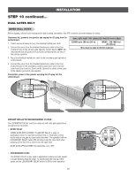
INSTALLATION STEP 6 continued... INSTALL ENTRAPMENT PROTECTION There are three options for wiring the entrapment protection devices depending on the specific device and how the device will function. Refer to the wiring diagram or the specific entrapment protection device manual for more information. These entrapment protection device inputs are for monitored devices, which include pulsed photoelectric sensors, resistive edge sensors, and pulsed edge sensors. NOTE: Only one monitored entrapment protection device may be wired to each input. CLOSE EYES/INTERRUPT (2 Terminals) The CLOSE EYES/INTERRUPT input is for photoelectric sensor entrapment protection for the close direction. When an obstruction is sensed during gate closing the gate will open to the full open position and resets the Timer-to-Close. This input will be disregarded during gate opening. CLOSE EDGE (2 Terminals) The CLOSE EDGE input is for edge sensor entrapment protection for the close direction. When an obstruction is sensed during gate closing the gate will reverse for 4 seconds then stop, disengaging the Timer-to-Close. This input will be disregarded during gate opening. OPEN EYES/EDGE (2 Terminals) The OPEN EYES/EDGE input is for photoelectric sensor or edge sensor entrapment protection for the open direction. When an obstruction is sensed during gate opening the gate will reverse for 4 seconds then stop. This input will be disregarded during gate closing. COM LINK BA Close Photoelectric Sensors Close Edge Open Photoelectric Sensors OR Open Edge AC & BATT FAIL BACKDRIVE STEP 7 EARTH GROUND ROD Use the proper earth ground rod for your local area. The ground wire must be a single, whole piece of wire. Never splice two wires for the ground wire. If you should cut the ground wire too short, break it, or destroy its integrity, replace it with a single wire length. 1. Install the earth ground rod within 3 feet of the operator. 2. Run wire from the earth ground rod to the operator. NOTE: If the operator is not grounded properly the range of the remote controls will be reduced and the operator will be more susceptible to lightning and surge damage. 15 To Operator Check national and local codes for proper depth
-
 1
1 -
2
-
3
-
4
-
5
-
6
-
7
-
8
-
9
-
10
-
 11
11 -
 12
12 -
 13
13 -
 14
14 -
 15
15 -
 16
16 -
 17
17 -
 18
18 -
 19
19 -
 20
20 -
 21
21 -
22
-
23
-
24
-
25
-
26
-
27
-
28
-
29
-
30
-
31
-
32
-
33
-
34
-
35
-
36
-
37
-
38
-
39
-
40
-
41
-
42
-
43
-
44
-
45
-
46
-
47
-
48
-
49
-
50
-
51
-
52
-
53
-
54
-
55
-
56
 |
 |
