LiftMaster CSW24VDC CSW24VDC Installation Manual - Page 18
Step 8 Continued...ac Power Switch, Step 9 Connect Batteries, Ac Power Switch
 |
View all LiftMaster CSW24VDC manuals
Add to My Manuals
Save this manual to your list of manuals |
Page 18 highlights
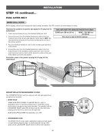
INSTALLATION STEP 8 continued... AC POWER SWITCH The AC Power switch on the operator will turn the incoming 120/240 Vac power ON or OFF. The operator's AC Power switch ONLY turns off AC power to the control board and DOES NOT turn off battery power. AC Power Switch STEP 9 CONNECT BATTERIES 7AH BATTERIES The batteries are charged in the circuit by the integrated transformer. The batteries are for battery backup. 1. Turn OFF AC power to the operator. 2. Unplug the J15 plug labeled BATT on the control board by squeezing the plug and pulling it from the control board. This disconnects the ac/dc power to the control board. 3. Connect a jumper between the positive (+) terminal of one battery to the negative terminal (-) of the other battery. 4. Connect the red wire from the J15 plug to the positive (+) terminal of the battery. 5. Connect the black wire from the J15 plug to the negative (-) terminal of the battery. 6. Plug the J15 plug back into the control board. This will power up the control board. NOTE: You may see a small spark when plugging the J15 plug into the board. 7. Turn ON AC power to the operator. 8. Turn ON the AC power switch on the operator. J15 Plug 17 Red Wire Jumper Black Wire
-
 1
1 -
2
-
3
-
4
-
5
-
6
-
7
-
8
-
9
-
10
-
11
-
12
-
 13
13 -
 14
14 -
 15
15 -
 16
16 -
 17
17 -
 18
18 -
 19
19 -
 20
20 -
 21
21 -
 22
22 -
 23
23 -
24
-
25
-
26
-
27
-
28
-
29
-
30
-
31
-
32
-
33
-
34
-
35
-
36
-
37
-
38
-
39
-
40
-
41
-
42
-
43
-
44
-
45
-
46
-
47
-
48
-
49
-
50
-
51
-
52
-
53
-
54
-
55
-
56
 |
 |
