LiftMaster CSW24VDC CSW24VDC Installation Manual - Page 17
Step 8 Power Wiring, Power Wiring - solar
 |
View all LiftMaster CSW24VDC manuals
Add to My Manuals
Save this manual to your list of manuals |
Page 17 highlights
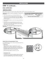
INSTALLATION To reduce the risk of SEVERE INJURY or DEATH: • ANY maintenance to the operator or in the area near the operator MUST NOT be performed until disconnecting the electrical power (AC or solar and battery) and locking-out the power via the operator power switch. Upon completion of maintenance the area MUST be cleared and secured, at that time the unit may be returned to service. • Disconnect power at the fuse box BEFORE proceeding. Operator MUST be properly grounded and connected in accordance with national and local electrical codes. NOTE: The operator should be on a separate fused line of adequate capacity. • ALL electrical connections MUST be made by a qualified individual. • DO NOT install ANY wiring or attempt to run the operator without consulting the wiring diagram. We recommend that you install an edge sensor BEFORE proceeding with the control station installation. • ALL power wiring should be on a dedicated circuit and well protected. The location of the power disconnect should be visible and clearly labeled. • ALL power and control wiring MUST be run in separate conduit. STEP 8 POWER WIRING This operator can be wired for either 120 Vac or 240 Vac or a solar panel (not provided). Follow the directions according to your application. For dual gate applications, power will have to be connected to each operator. Main power supply and control wiring MUST be run in separate conduits. SOLAR APPLICATIONS: For solar applications refer to Solar Panels section in the Appendix, pages 45-48. Follow the directions according to your application. NOTE: If using an external receiver use shielded wire for the connections and mount the receiver away from the operator to avoid interference with the operator. AMERICAN WIRE GAUGE (AWG) 14 12 10 8 6 4 MAXIMUM WIRE LENGTH (120 VAC) 130 feet 205 feet 325 feet 520 feet 825 feet 1312 feet NOTE: Use copper conductors ONLY. 240 VAC ONLY Outlet Housing The accessory outlet is disabled and cannot be used with the 240 Vac option. 1. Remove the outlet housing from the electrical box by removing the screws (2). 2. Pull the outlet housing out and locate the power wiring connector on the EMI board. 3. Unplug the power wiring connector from the 120 Vac socket (factory default location) and plug it into the 240 Vac socket. 4. Replace the outlet housing by securing with the screws. The operator is now set for 240 Vac operation. 240 Vac Socket EMI Board Power Wiring Connector (120 Vac Socket, factory default) MAXIMUM WIRE LENGTH (240 VAC) 260 feet 410 feet 650 feet 1040 feet 1650 feet 2624 feet 120 VAC AND 240 VAC 1. Turn off the AC power from the main power source circuit breaker. 2. Run the AC power wires to the operator. 3. Remove the junction box cover. 4. Connect the green wire to the earth ground rod and AC ground using a wire nut. NOTE: The earth ground rod can be grounded to the chassis. 5. Connect the white wire to NEUTRAL using a wire nut. 6. Connect the black wire to HOT using a wire nut. 7. Replace the junction box cover. Ensure the wires are not pinched. Junction Box Cover 16
-
 1
1 -
2
-
3
-
4
-
5
-
6
-
7
-
8
-
9
-
10
-
11
-
 12
12 -
 13
13 -
 14
14 -
 15
15 -
 16
16 -
 17
17 -
 18
18 -
 19
19 -
 20
20 -
 21
21 -
 22
22 -
23
-
24
-
25
-
26
-
27
-
28
-
29
-
30
-
31
-
32
-
33
-
34
-
35
-
36
-
37
-
38
-
39
-
40
-
41
-
42
-
43
-
44
-
45
-
46
-
47
-
48
-
49
-
50
-
51
-
52
-
53
-
54
-
55
-
56
 |
 |
