LiftMaster GH GH LOGIC 3 Manual - Page 10
Power Wiring & Ground Wiring - wiring diagram
 |
View all LiftMaster GH manuals
Add to My Manuals
Save this manual to your list of manuals |
Page 10 highlights
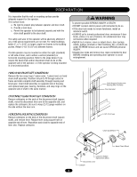
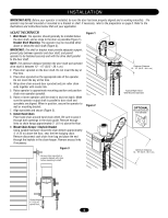
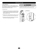
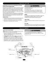
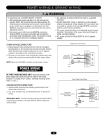
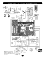
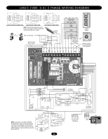
NG P O W E R W I R I NWGA&RNG IRNOGU N D W I R I N G N WARNING To reduce the risk of SEVERE INJURY or DEATH: • ANY maintenance to the operator or in the area near the operator MUST NOT be performed until disconnecting the electrical power and locking-out the power via the operator power switch. Upon completion of maintenance the area MUST be cleared and secured, at that time the unit may be returned to service. • Disconnect power at the fuse box BEFORE proceeding. Operator MUST be properly grounded and connected in accordance with local electrical codes. The operator should be on a separate fused line of adequate capacity. • ALL electrical connections MUST be made by a qualified individual. • DO NOT install ANY wiring or attempt to run the operator without consulting the wiring diagram. We recommend that you install an optional reversing edge BEFORE proceeding with the control station installation. • ALL power wiring should be on a dedicated circuit and well protected. The location of the power disconnect should be visible and clearly labeled. • ALL power and control wiring MUST be run in separate conduit. MENT POWER WIRING CONNECTIONS AVERTISSEMENT Single Phase Power Wiring 1. Connect power wires coming from the main to the captive N AVERTISSEMENT terminal block in the electrical box enclosure marked with the label. All power and control wiring must be run in separate conduit in accordance with local electrical codes. 2. Be sure to run all power wires through the conduit hole in the electrical box enclosure marked with the label shown below. Line Power 115/230 Vac Single Phase Hot Neutral Gnd NOTE: Must use #14 AWG or thicker wire for power wiring. ON THREE PHASE MACHINES ONLY: Incorrect phasing of the power supply will cause the motor to rotate in the wrong direction. To change motor rotation, exchange incoming power leads L1 and L2. Three Phase Power Wiring GROUND WIRING CONNECTIONS NCIA1. Connect earth ground to the chassis ground screwAin DtheVERTENCIA electrical box enclosure. ÓN ADVERTENCIA 2. Use same conduit entry into the electrical box as the power wiring. Line Power 208/230/380/460/575 Vac Three Phase IMPORTANT NOTE: This unit must be properly grounded. Failure to properly ground this unit could result in electric shock and serious injury. Phase 1 Phase 2 Phase 3 Gnd 10
-
 1
1 -
2
-
3
-
4
-
 5
5 -
 6
6 -
 7
7 -
 8
8 -
 9
9 -
 10
10 -
 11
11 -
 12
12 -
 13
13 -
 14
14 -
 15
15 -
16
-
17
-
18
-
19
-
20
-
21
-
22
-
23
-
24
-
25
-
26
-
27
-
28
-
29
-
30
-
31
-
32
-
33
-
34
-
35
-
36
 |
 |
