LiftMaster GH GH LOGIC 3 Manual - Page 31
Electrical Box Logic Ver 3.0 - 10 11 2
 |
View all LiftMaster GH manuals
Add to My Manuals
Save this manual to your list of manuals |
Page 31 highlights
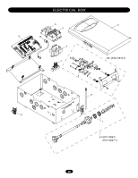
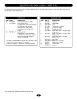
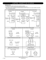
ELECTRICAL BOX LOGIC (VER 3.0) For replacement of electrical box, motor or brake components be sure to match model number of your unit to kit number below to ensure proper voltage requirements. SERVICE KITS ITEM PART # K1 K72-10047 K72-10047-1 K2 K72-12515-1 DESCRIPTION Limit shaft kit (1/2 up to 2HP) Limit shaft kit (3HP) Complete with: Limit shaft, limit nuts, limit bearings, limit sprocket, interrupter cup, shim washers, compression ring, roll pin, and e-rings. Limit switch kit Complete with: Limit nut retainer, switch plates, backup plate, depress plates, limit switches, standoffs, screws, and locknuts. * To order a complete electrical box kit, add a K- prefix to the model number of your operator. For example: GH5011L3 (Operator) = K-GH5011L3 (Electrical box kit) ITEM 1 2 3 4 5 6 7 8 9 10 11 INDIVIDUAL PARTS PART # DESCRIPTION 13-10024 Limit nut 23-10041 Limit switch K75-32268 Cover 21-14182 Transformer, 115/230V 21-35057 Transformer, 460V 21-5575 Transformer, 575V 29-31244 Relay 24Vdc DPST - (A and B relay) all operators 29-31245 Relay 12Vdc SPDT - (C and D relay) 3 Phase only 29-31229 Relay 24Vdc SPDT - (C relay) 1 Phase only K74-31243 MOV 580V K79-15016-1 RPM sensor assembly K1A5729 Logic board - Logic 3 K2A761 Coaxial cable K1C3196-3 Antenna *Non stocked item. Please allow additional delivery time. 31
-
 1
1 -
2
-
3
-
4
-
5
-
6
-
7
-
8
-
9
-
10
-
11
-
12
-
13
-
14
-
15
-
16
-
17
-
18
-
19
-
20
-
21
-
22
-
23
-
24
-
25
-
 26
26 -
 27
27 -
 28
28 -
 29
29 -
 30
30 -
 31
31 -
 32
32 -
 33
33 -
 34
34 -
 35
35 -
 36
36
 |
 |