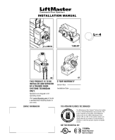
LiftMaster GH GT- Logic 4 Installation Manual - Page 2

Table Of Contents - model

Page 2 highlights

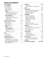
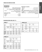
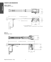
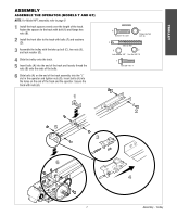
TABLE OF CONTENTS SAFETY INFORMATION 3 TROLLEY OPERATORS 4-12 Carton Inventory 4 Operator Specifications 4-5 Maximum Door Area 5 Weights and Dimensions 6 ASSEMBLY 7-9 Assemble the Operator (Models T and GT 7 Install the Chain (Models T and GT 8 Assemble the Operator (Model APT 9 TYPICAL INSTALLATION 10-12 Install the Header Bracket 10 Attach the Track to the Header Bracket 11 Hang the Operator 11 Attach the Door Arm 12 HOIST AND JACKSHAFT OPERATORS 13-17 Carton Inventory 13 Operator Specifications 13-14 Maximum Door Area 14 Weights and Dimensions 15 ASSEMBLY 16 Assemble the Operator 16 TYPICAL INSTALLATION 16-17 Determine Mounting Location 16 Mounting 17 Install the Manual Disconnect 17 WIRING 18-19 Power and Ground 18 Control Station 19 ENTRAPMENT PROTECTION 20-22 LiftMaster Monitored Entrapment Protection (LMEP 20 Install the Photoelectric Sensors (Provided 21 Mount the Photoelectric Sensors (Provided 22 Wire the LiftMaster Monitored Entrapment Protection (LMEP) Devices 22 ADJUSTMENT 23-24 Limit Adjustment 23 Clutch Adjustment (Belt Drive Model Operators 24 TESTING 25 MANUAL RELEASE 26-27 Emergency Disconnect System Model GT and T 26 Emergency Disconnect System Model APT 26 Emergency Disconnect System Model H, GH, J, and HJ 27 PROGRAMMING 28-35 Introduction to Programming 28 Determine and Set Wiring Type 29 Programming Remote Controls 30-31 Maintenance Alert System (MAS 32 Open Mid Stop 33 Timer-To-Close 33-34 Car Dealer Mode 34 Maximum Run Timer (MRT 35 Resetting Factory Defaults - Clearing Memory 35 MAINTENANCE 36 Maintenance Schedule 36 Life of Operator Feature (Odometer/Cycle Counter) . . . . 36 Brake (If Present 36 How to Order Repair Parts 36 TROUBLESHOOTING 37-40 Diagnostic Chart 37 Troubleshooting Guide 38 Troubleshooting Error Codes 39 Troubleshooting Radio Functionality 40 WIRING DIAGRAMS 41-42 Logic (Ver. 4.0) 1 Phase Wiring Diagram 41 Logic (Ver. 4.0) 3 Phase Wiring Diagram 42 ACCESSORIES 43 CONTROL CONNECTION DIAGRAM BACK COVER Table of contents 2

  • 1
  • 2
  • 3
  • 4
  • 5
  • 6
  • 7
  • 8
  • 9
  • 10
  • 11
  • 12
  • 13
  • 14
  • 15
  • 16
  • 17
  • 18
  • 19
  • 20
  • 21
  • 22
  • 23
  • 24
  • 25
  • 26
  • 27
  • 28
  • 29
  • 30
  • 31
  • 32
  • 33
  • 34
  • 35
  • 36
  • 37
  • 38
  • 39
  • 40
  • 41
  • 42
  • 43
  • 44

TABLE OF CONTENTS
SAFETY INFORMATION
3
TROLLEY OPERATORS
4-12
Carton Inventory
. . . . . . . . . . . . . . . . . . . . . . . . . . . . . . . 4
Operator Specifications
. . . . . . . . . . . . . . . . . . . . . . . . .4-5
Maximum Door Area . . . . . . . . . . . . . . . . . . . . . . . . . . . . 5
Weights and Dimensions . . . . . . . . . . . . . . . . . . . . . . . . . 6
ASSEMBLY
. . . . . . . . . . . . . . . . . . . . . . . . . . . . . . . . . . .7-9
Assemble the Operator (Models T and GT) . . . . . . . . . 7
Install the Chain (Models T and GT). . . . . . . . . . . . . . . 8
Assemble the Operator (Model APT) . . . . . . . . . . . . . . 9
TYPICAL INSTALLATION
. . . . . . . . . . . . . . . . . . . . . .10-12
Install the Header Bracket
. . . . . . . . . . . . . . . . . . . . . 10
Attach the Track to the Header Bracket . . . . . . . . . . . 11
Hang the Operator . . . . . . . . . . . . . . . . . . . . . . . . . . . 11
Attach the Door Arm
. . . . . . . . . . . . . . . . . . . . . . . . . 12
HOIST AND JACKSHAFT OPERATORS
13-17
Carton Inventory
. . . . . . . . . . . . . . . . . . . . . . . . . . . . . . 13
Operator Specifications
. . . . . . . . . . . . . . . . . . . . . . .13-14
Maximum Door Area
. . . . . . . . . . . . . . . . . . . . . . . . . . . 14
Weights and Dimensions . . . . . . . . . . . . . . . . . . . . . . . . 15
ASSEMBLY
. . . . . . . . . . . . . . . . . . . . . . . . . . . . . . . . . . . 16
Assemble the Operator
. . . . . . . . . . . . . . . . . . . . . . . 16
TYPICAL INSTALLATION
. . . . . . . . . . . . . . . . . . . . . .16-17
Determine Mounting Location . . . . . . . . . . . . . . . . . . 16
Mounting . . . . . . . . . . . . . . . . . . . . . . . . . . . . . . . . . . 17
Install the Manual Disconnect . . . . . . . . . . . . . . . . . . 17
WIRING
18-19
Power and Ground . . . . . . . . . . . . . . . . . . . . . . . . . . . . . 18
Control Station . . . . . . . . . . . . . . . . . . . . . . . . . . . . . . . . 19
ENTRAPMENT PROTECTION
20-22
LiftMaster Monitored Entrapment
Protection (LMEP) . . . . . . . . . . . . . . . . . . . . . . . . . . . . . 20
Install the Photoelectric Sensors (Provided)
. . . . . . . . . 21
Mount the Photoelectric Sensors (Provided) . . . . . . . . . 22
Wire the LiftMaster Monitored Entrapment
Protection (LMEP) Devices
. . . . . . . . . . . . . . . . . . . . . . 22
ADJUSTMENT
23-24
Limit Adjustment . . . . . . . . . . . . . . . . . . . . . . . . . . . . . . 23
Clutch Adjustment (Belt Drive Model Operators) . . . . . . 24
TESTING
25
MANUAL RELEASE
26-27
Emergency Disconnect System Model GT and T . . . . . . 26
Emergency Disconnect System Model APT . . . . . . . . . . 26
Emergency Disconnect System
Model H, GH, J, and HJ . . . . . . . . . . . . . . . . . . . . . . . . . 27
PROGRAMMING
28-35
Introduction to Programming. . . . . . . . . . . . . . . . . . . . . 28
Determine and Set Wiring Type . . . . . . . . . . . . . . . . . . . 29
Programming Remote Controls . . . . . . . . . . . . . . . . .30-31
Maintenance Alert System (MAS)
. . . . . . . . . . . . . . . . . 32
Open Mid Stop . . . . . . . . . . . . . . . . . . . . . . . . . . . . . . . . 33
Timer-To-Close
. . . . . . . . . . . . . . . . . . . . . . . . . . . . .33-34
Car Dealer Mode. . . . . . . . . . . . . . . . . . . . . . . . . . . . . . . 34
Maximum Run Timer (MRT)
. . . . . . . . . . . . . . . . . . . . . 35
Resetting Factory Defaults - Clearing Memory . . . . . . . . 35
MAINTENANCE
36
Maintenance Schedule . . . . . . . . . . . . . . . . . . . . . . . . . . 36
Life of Operator Feature (Odometer/Cycle Counter) . . . . 36
Brake (If Present). . . . . . . . . . . . . . . . . . . . . . . . . . . . . . 36
How to Order Repair Parts . . . . . . . . . . . . . . . . . . . . . . . 36
TROUBLESHOOTING
37-40
Diagnostic Chart. . . . . . . . . . . . . . . . . . . . . . . . . . . . . . . 37
Troubleshooting Guide. . . . . . . . . . . . . . . . . . . . . . . . . . 38
Troubleshooting Error Codes . . . . . . . . . . . . . . . . . . . . . 39
Troubleshooting Radio Functionality . . . . . . . . . . . . . . . 40
WIRING DIAGRAMS
41-42
Logic (Ver. 4.0) 1 Phase Wiring Diagram. . . . . . . . . . . . 41
Logic (Ver. 4.0) 3 Phase Wiring Diagram. . . . . . . . . . . . 42
ACCESSORIES
43
CONTROL CONNECTION DIAGRAM
BACK COVER
Table of contents
2