LiftMaster GH GT- Logic 4 Installation Manual - Page 22
CPS-U and CPS-UN4, CPS-EI - logic 5
 |
View all LiftMaster GH manuals
Add to My Manuals
Save this manual to your list of manuals |
Page 22 highlights
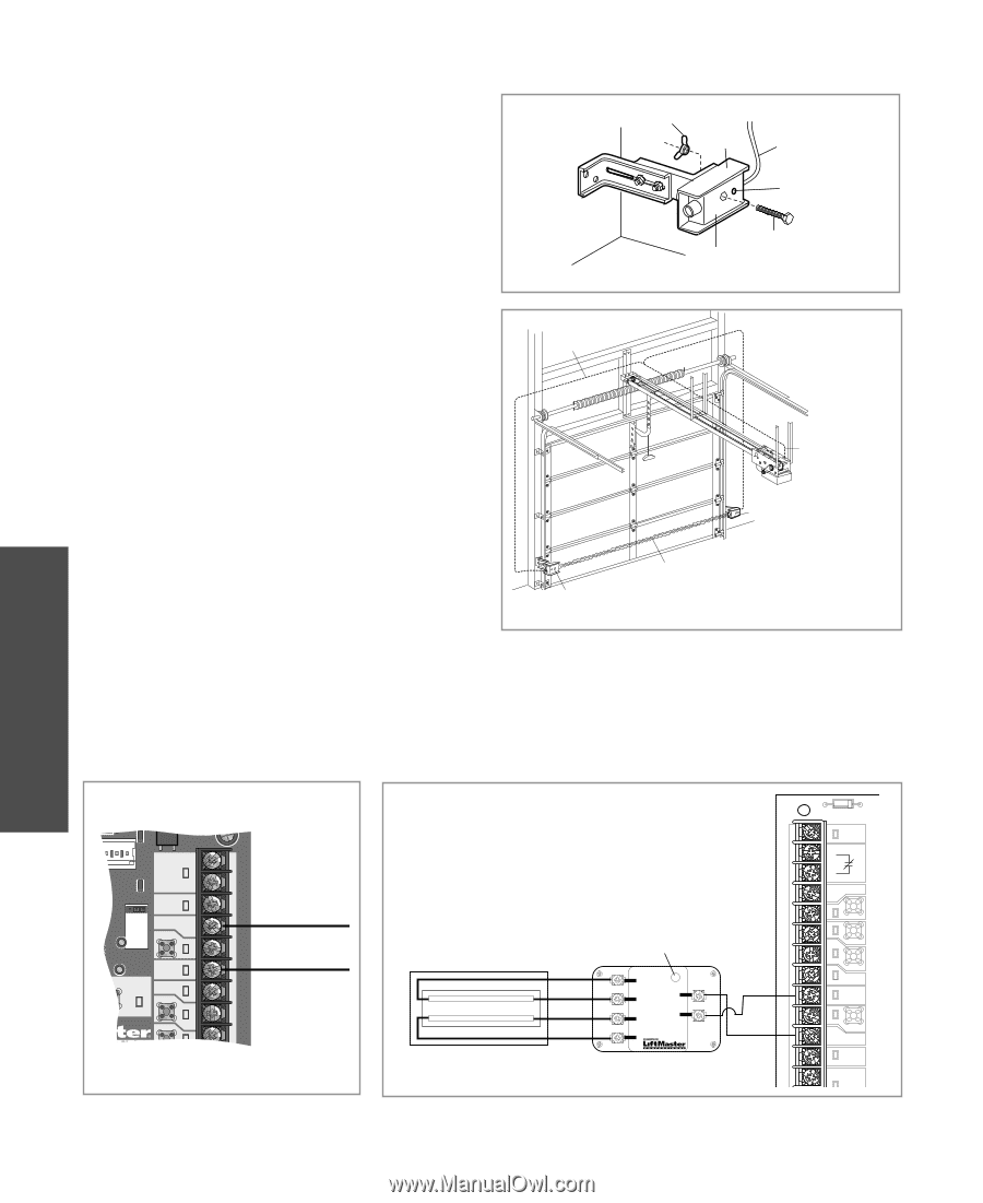
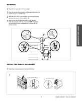
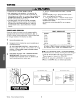
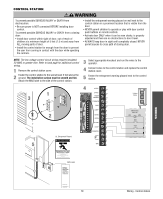
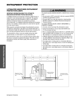
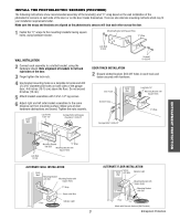
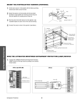
MOUNT THE PHOTOELECTRIC SENSORS (PROVIDED) 1 Center each sensor in the bracket with the lenses pointing toward each other across the door. 2 Attach the sensors to the brackets with the provided hardware. Finger tighten the receiving sensor wing nut. Securely tighten the sending sensor wing nut. 3 Run the wires from both sensors to the operator. Use insulated staples to secure wire to the wall and ceiling. 4 Connect the sensor wires to the operator (see below). Bell Wire Wing Nut "C" Wrap Wire Indicator Light Sensor Hex Bolt 1/4-20x1-1/2" ENTRAPMENT PROTECTION Secure wire with insulated staples Connect wire to Operator (refer to following page) Photoelectric Sensor 6" (15 cm) max. above floor Invisible Light Beam Protection Area Photoelectric Sensor 6" (15 cm) max. above floor WIRE THE LIFTMASTER MONITORED ENTRAPMENT PROTECTION (LMEP) DEVICES 1 Connect the LiftMaster Monitored Entrapment Protection (LMEP) device to the logic board according to the models shown below: CPS-U and CPS-UN4 CPS-EI POWER 24VAC TIMER DEFEAT COMMON MAS LMEP EDGE OPEN CLOSE STOP COMMON SBC 24VAC POWER 24VAC TIMER DEFEAT COMMON MAS 3-PHASE 1-PHASE LMEP: TTC TIMER ENABLE EDGE: OPEN 3 CLOSE TS FSTS DIAG STOP COMMON White (Blue) White/Black (Brown) 4-Wire Sensing Edge Black Black White White Green LED CPS-EI E1 LMEP2 E2 LMEP1 E3 E4 40-34141-1 Entrapment Protection 22
-
 1
1 -
2
-
3
-
4
-
5
-
6
-
7
-
8
-
9
-
10
-
11
-
12
-
13
-
14
-
15
-
16
-
 17
17 -
 18
18 -
 19
19 -
 20
20 -
 21
21 -
 22
22 -
 23
23 -
 24
24 -
 25
25 -
 26
26 -
 27
27 -
28
-
29
-
30
-
31
-
32
-
33
-
34
-
35
-
36
-
37
-
38
-
39
-
40
-
41
-
42
-
43
-
44
 |
 |