LiftMaster LA412 LA412 Manual
LiftMaster LA412 Manual
 |
View all LiftMaster LA412 manuals
Add to My Manuals
Save this manual to your list of manuals |
LiftMaster LA412 manual content summary:
- LiftMaster LA412 | LA412 Manual - Page 1
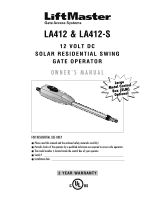
DC SOLAR RESIDENTIAL SWING GATE OPERATOR OWNER'S MANUAL MeBtOoLaaxplrtC(giXooennLMatrl)ol FOR RESIDENTIAL USE ONLY ■ Please read this manual and the enclosed safety materials carefully! ■ Periodic checks of the operator by a qualified technician are required to ensure safe operation. ■ The model - LiftMaster LA412 | LA412 Manual - Page 2
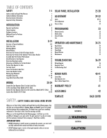
Reset Button Remote Control Sleep Mode Manual Release Maintenance TROUBLESHOOTING Wiring Diagram Diagnostic Chart Troubleshooting Chart REPAIR PARTS Control Box Gate Operator Arm How to Order Repair Parts WARRANTY POLICY ACCESSORIES TEMPLATE SAFETY » SAFETY SYMBOL AND SIGNAL WORD REVIEW When you - LiftMaster LA412 | LA412 Manual - Page 3
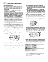
all instructions. 2. The gate operator is intended for use with Class I vehicular swing gates. Class I denotes a vehicular gate operator (or system) intended for use in a home of one to four single family dwellings, or a garage or parking area associated therewith. Install the gate operator only - LiftMaster LA412 | LA412 Manual - Page 4
guide, refer to ASTM F2200 for panel types. 1.5 An existing gate latch shall be disabled when a manually operated gate is retrofitted with a powered gate operator. 3.2 The following provisions shall apply to Class IV vehicular horizontal slide gates: 1.6 A gate latch shall not be installed - LiftMaster LA412 | LA412 Manual - Page 5
ANY service or maintenance. • DO NOT connect solar panel(s) when power supply is connected. • DO NOT connect more than 30W (3 solar panels). To reduce the risk of FIRE or INJURY to persons use ONLY LiftMaster part 29-NP712 for replacement batteries. ADJUSTMENT Without a properly installed safety - LiftMaster LA412 | LA412 Manual - Page 6
entrance. • Disconnect ALL power BEFORE performing ANY maintenance. • SAVE THESE INSTRUCTIONS. TROUBLESHOOTING To protect against fire and electrocution: • DISCONNECT power and battery BEFORE installing or servicing operator. For continued protection against fire: • Replace ONLY with fuse of - LiftMaster LA412 | LA412 Manual - Page 7
open, accessory kit 50-19503 is required. Pull-to-Open Bracket Model LA412 (1) Model LA412-S (2) Gate Bracket Model LA412 (1) Model LA412-S (2) Post Bracket Model LA412 (1) Model LA412-S (2) 12V 10W Solar Panel Model SOLPNL10W12V (1) Cable Ties (4) Standard Control Box (1) with 2 Batteries - LiftMaster LA412 | LA412 Manual - Page 8
sizes for the control boxes are: 1/4" - standard control box 3/8" - XLM control box PHOTOELECTRIC SENSORS The Model 50-220 photoelectric sensors are intended for installation with the operators covered in this manual. To order call 1-800-528-2806 or visit www.liftmaster.com. LA412-S ONLY: CONDUIT - LiftMaster LA412 | LA412 Manual - Page 9
OF TYPICAL INSTALLATION LEFT-HAND GATE Warning Sign Antenna Control Box with Batteries Solar Panel (Facing South) Hinge Post Bracket Gate Bracket PVC Conduit (not provided) to protect the power cable for solar and low voltage wire from lawn mowers and string trimmers. Operator Operator Cable - LiftMaster LA412 | LA412 Manual - Page 10
OF TYPICAL INSTALLATION DUAL GATE Solar Panel (Facing South) Antenna Warning Sign Hinge Post Bracket Gate Bracket Gate 1 Control Box with Batteries Operator Cable Gate 2 Junction Box Extension Cable Photoelectric Sensors PVC Conduit (not provided) to protect the power cable for solar and - LiftMaster LA412 | LA412 Manual - Page 11
swing freely and be supported entirely by its hinges. D MOUNTING OPTIONS Mounting locations vary depending on type and style of your gate. Minimum distance from the ground should not be less than 4 inches (10.2 cm) from the bottom of the gate operator arm. RECOMMENDED: = Gate post bracket mounting - LiftMaster LA412 | LA412 Manual - Page 12
lever 180° counterclockwise. The operator is now in manual mode. Key 1 2 DETERMINE POSITION OF THE PULL-TO-OPEN BRACKET The Pull-To-Open bracket can be assembled to work on a Left-Hand or a Right-Hand gate. 1 Review the gate types and select the type of installation you will require. NOTE - LiftMaster LA412 | LA412 Manual - Page 13
(PULL-TO-OPEN) + ATTACH BRACKETS TO GATE OPERATOR All the illustrations on the following pages display a typical Left-Hand Gate installation. For push-to-open installations refer to instructions with push-to-open kit 50-19503. ASSEMBLE GATE POST BRACKET (PULL-TO-OPEN) 1 Assemble gate post bracket - LiftMaster LA412 | LA412 Manual - Page 14
dimensions for the Pull-To-Open bracket. NOTE: It may be necessary to add shims (angle iron, sheets of metal or wood) to the gate post to achieve the required dimensions. Gate Post Gate Hinge Point Gate Post Gate Hinge Point Gate Post Gate Hinge Point Operator Hinge Point 7" (18 cm) 7" (18 - LiftMaster LA412 | LA412 Manual - Page 15
INSTALLATION » POSITION GATE OPERATOR ON GATE POSITION GATE OPERATOR ON GATE NOTE: The post bracket assembly can be mounted several places on the gate post. Refer to page 10 for mounting options. 1 Open the gate to desired open position (no greater than 100°) and hold operator against gate. 2 - LiftMaster LA412 | LA412 Manual - Page 16
INSTALLATION » TEST GATE TRAVEL + SECURE POST BRACKET TO GATE POST TEST GATE TRAVEL NOTE: If gate does not open and close completely adjust the position of the 1 gate bracket and mark new mounting holes. 1 Manually open and close the gate. 2 Ensure that the operator does not bind against the - LiftMaster LA412 | LA412 Manual - Page 17
Area 3 Manually move the gate to verify that it opens and closes fully. 1 Operator Angle Iron OR Wood OR Flat Bar Welder (Optional) Hex Nut Lock Washer Flat Washer 2 Gate Bracket Hex Bolt 3 WARNING SIGN PLACEMENT Warning signs MUST be installed on both sides of the gate and in - LiftMaster LA412 | LA412 Manual - Page 18
gate operator. Mount the control box as high as possible for best radio reception. 1 Remove screws and open the control box. 2 Disconnect the reset button, alarm, and coaxial connector. 3 Loosen screws to remove the control board and mounting bracket. 4 Remove the control board. 5 Remove batteries - LiftMaster LA412 | LA412 Manual - Page 19
INSTALLATION » STANDARD CONTROL BOX INSTALL THE CONTROL BOARD NOTE: Make sure the battery leads are on the left side of the control box and not pinched. 1 Attach the antenna. 2 Reinstall the batteries, control board, alarm and reset button. 1 2 Coaxial Connector Reset Button Connections Alarm 18 - LiftMaster LA412 | LA412 Manual - Page 20
/SOLAR INSTALLATION » LARGE METAL CONTROL BOX (XLM) MOUNT THE CONTROL BOX (XLM) The control box MUST be mounted within 5 feet (1.52 m) of the gate operator. 1 90° Mount the control box as high as possible for best radio reception. LEARN XMITTER ON OFF LOCK / BIPA RT DELAY CLOSE EDGE OPEN - LiftMaster LA412 | LA412 Manual - Page 21
the control box. 4 Extend the operator cable and wires to the Gate 1 connector and connect as shown. 5 Tighten watertight connector nut. NC 4 Z1 GATE 1 10A 32V BRN D1Ø GRN WHT YEL BLU RED Z12 ACCESSORY POWER GATE 1 BRN GRN WHT U4 YEL BLU RED 3 MAX C13 C4 F6 F2 FUSE OPEN Nut - LiftMaster LA412 | LA412 Manual - Page 22
in dual gate installations, one gate will need to open first and close second. This would happen if there was an ornamental overhang on one gate or if using a solenoid lock, for example. This gate is called the Primary gate and needs to be connected to Gate 1 connections on the control board. Thus - LiftMaster LA412 | LA412 Manual - Page 23
level (grade) Gate Operator (Gate 1) 1 PVC conduit (not provided) to protect the power cable for solar panel and low voltage wire from lawn mowers and string trimmers. Terminal blocks can be removed to simplify wiring. 3 ACCESSORY APCCOEWSSEORRY POWER R9Ø R9Ø 242V4V P1 GATE 2 GATE 2 BRN - LiftMaster LA412 | LA412 Manual - Page 24
WIRING » JUNCTION BOX (MODEL LA412-S ONLY) JUNCTION BOX The following items are required to complete the junction box installation: • 4 x 4 Junction Box with 3/4" NPT threaded port holes • Screws • PVC Conduit 1 Open the junction box by removing screws (4) and set aside. 2 Mount the junction box - LiftMaster LA412 | LA412 Manual - Page 25
WIRING » JUNCTION BOX (MODEL LA412-S ONLY) 6 Remove terminals from operator cable. Strip wires and twist like colored wires together with wire nuts. 6 Operator Cable Wire Nut Green Brown Brown Red Green White Yellow Blue White Yellow Blue Red Extension Cable 7 Put wires inside of junction - LiftMaster LA412 | LA412 Manual - Page 26
FOR SOLAR PANEL(S) The solar panel(s) must be located in an open area clear of obstructions and shading for the entire day. The solar panel(s) comes with a 10 foot (3 m) cable. If a location near the control box cannot be found, an additional cable will be required. The LA412 Solar Gate Operator is - LiftMaster LA412 | LA412 Manual - Page 27
it. South DO NOT install solar panel near potential shading or obstructions that will block the panel during any part of the day. 180° Sun's Position South TIP: To optimize the system for winter operation the angle can be increased an additional 15° (solar panel(s) sits more vertical). 26 - LiftMaster LA412 | LA412 Manual - Page 28
SOLAR PANEL INSTALLATION » INSTALL THE SOLAR PANEL(S) INSTALL THE SOLAR PANEL(S) Solar panel(s) MUST be installed facing south. Use a compass to determine direction. 1 Position solar bracket on mounting surface. Mark and drill holes. 1 2 Insert two bolts into the track located on the back of the - LiftMaster LA412 | LA412 Manual - Page 29
SOLAR PANEL INSTALLATION » CONNECT SOLAR PANEL(S) TO OPERATOR CONTROL BOX + CONNECT BATTERIES CONNECT SOLAR PANEL(S) TO OPERATOR CONTROL BOX 1 Open the control box cover. 2 Disconnect all power and batteries from the control board. 3 Run the solar panel cable to the bottom of the control box. - LiftMaster LA412 | LA412 Manual - Page 30
control board beeps and the SET OPEN LIMIT and SET CLOSE LIMIT LEDs stop blinking, programming is now complete. (If the SET OPEN LIMIT LED continues to blink, repeat programming. If the problem continues, see Troubleshooting section.) Test the limits by pressing the SBC to open and close the gate - LiftMaster LA412 | LA412 Manual - Page 31
control board beeps and the SET OPEN LIMIT and SET CLOSE LIMIT LEDs stop blinking, programming is now complete. (If the SET OPEN LIMIT LED continues to blink, repeat programming. If the problem continues, see Troubleshooting section.) Test the limits by pressing the SBC to open and close the gate - LiftMaster LA412 | LA412 Manual - Page 32
control board beeps and the SET OPEN LIMIT and SET CLOSE LIMIT LEDs stop blinking, programming is now complete. (If the SET OPEN LIMIT LED continues to blink, repeat programming. If the problem continues, see Troubleshooting section.) Test the limits by pressing the SBC to open and close the gate - LiftMaster LA412 | LA412 Manual - Page 33
or the Single Button Control (SBC) button on the control board, open and then close the gate. 2 If the gate stops or reverses before reaching the fully open or closed position increase the force by turning the force control slightly. FORCE D4 D2 FORCE 2 OFF MAX 3 Run operator through a complete - LiftMaster LA412 | LA412 Manual - Page 34
this receiver and/or transmitter are prohibited, except for changing the code setting or replacing the battery. THERE ARE NO OTHER USER SERVICEABLE PARTS. Tested to Comply with FCC Standards FOR HOME OR OFFICE USE. Operation is subject to the following two conditions: (1) this device may not cause - LiftMaster LA412 | LA412 Manual - Page 35
on the control board will close the gate and return the operator to normal operation. REMOTE CONTROL Once the remote control has been programmed operator will operate as follows: When gate is in the closed position, activation of the remote control button will open the gate. During the open cycle - LiftMaster LA412 | LA412 Manual - Page 36
°. This locks the release lever. 3 Remove the key and store in a safe place. The operator is now engaged. 3 3 MAINTENANCE Disconnect power before servicing. DESCRIPTION External Entrapment Protection System Manual Release Gate Accessories Electrical Mounting Hardware Batteries Operator Warning - LiftMaster LA412 | LA412 Manual - Page 37
14 NOTE: Batteries MUST 8 be connected to operate. OPTIONAL TRANSFORMER SOLAR PANEL NOTE: 14.5 V output on transformer. To protect against fire and electrocution: • DISCONNECT power and battery BEFORE installing or servicing operato.r For continued protection against fire: • Replace ONYL with - LiftMaster LA412 | LA412 Manual - Page 38
of the battery. Replace the batteries (see accessories page). Dispose of old batteries properly. 4 FLASHES LOW BATTERY CAPACITY 5 FLASHES RPM REVERSAL GATE 1 OR IN MANUAL RELEASE MODE. WIRING TO THE OPERATOR IS DISCONNECTED OR DAMAGED Battery does not have the capacity to operate the gate operator - LiftMaster LA412 | LA412 Manual - Page 39
LEARN LIMITS. GATE DOES NOT FULLY OPEN OR CLOSE WHEN TRYING TO LEARN LIMITS. OPERATOR DOES NOT RESPOND TO SINGLE BUTTON (SBC) COMMAND. OPERATOR DOES NOT RESPOND TO REMOTE CONTROL COMMAND. • Power not connected. Make sure the AC/Solar input is connected and that at least one battery is connected - LiftMaster LA412 | LA412 Manual - Page 40
» TROUBLESHOOTING CHART OPERATOR DOES NOT RESPOND TO REMOTE CONTROL COMMAND. GATE STOPS AND REVERSES IMMEDIATELY AFTER IT STARTS MOVING. GATE OPENS BUT DOES NOT CLOSE. • Antenna not connected. Verify the antenna and coaxial cable are properly connected to the control board. • Remote control not - LiftMaster LA412 | LA412 Manual - Page 41
REPAIR PARTS » CONTROL BOX + GATE OPERATOR ARM CONTROL BOX Refer to the parts lists below for replacement parts available for your operator. If optional modifications and/or accessories are included with your operator, certain components may be added or removed from these lists. ITEM PART # - LiftMaster LA412 | LA412 Manual - Page 42
SPANS AMERICA FOR INSTALLATION AND SERVICE INFORMATION, CALL OUR TOLL FREE NUMBER 1-800-528-2806 www.liftmaster.com WHEN ORDERING REPAIR PARTS PLEASE SUPPLY THE FOLLOWING INFORMATION: PART NUMBER DESCRIPTION MODEL NUMBER ADDRESS ORDER TO: THE CHAMBERLAIN GROUP, INC. Technical Support Group 6050 - LiftMaster LA412 | LA412 Manual - Page 43
Watt Solar Kit: This kit is to replace or add a Solar Panel to the operator system. Up to three Solar Panels can be connected to the gate operator. OPEN CLOSE 50-19503 Wireless Gate Doorbell: Allows guests to ring a doorbell iOnPENthe house from the keypad. CLOSE Homeowner can open gate from - LiftMaster LA412 | LA412 Manual - Page 44
TEMPLATE FOR POST BRACKET MOUNTING 7 6 5 4 3 2 1 7 6 5 4 3 2 1 01-34491G © 2010, The Chamberlain Group, Inc. All Rights Reserved
-
 1
1 -
 2
2 -
 3
3 -
 4
4 -
 5
5 -
 6
6 -
 7
7 -
8
-
9
-
10
-
11
-
12
-
13
-
14
-
15
-
16
-
17
-
18
-
19
-
20
-
21
-
22
-
23
-
24
-
25
-
26
-
27
-
28
-
29
-
30
-
31
-
32
-
33
-
34
-
35
-
36
-
37
-
38
-
39
-
40
-
41
-
42
-
43
-
44
 |
 |
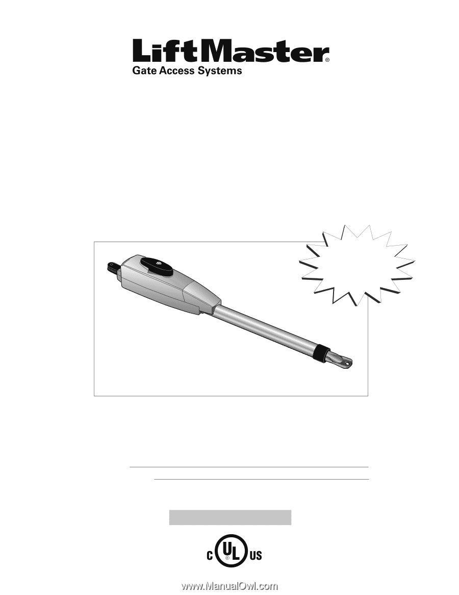
LA412
&
LA412-S
12 VOLT DC
SOLAR RESIDENTIAL SWING
GATE OPERATOR
O
W N E R ' S
M A N U A L
■
Please read this manual and the enclosed safety materials carefully!
■
Periodic checks of the operator by a qualified technician are required to ensure safe operation.
■
The model number is located inside the control box of your operator.
■
Serial #
■
Installation date
FOR RESIDENTIAL USE ONLY
2 YEAR WARRANTY
Large
Metal Control
Box (XLM)
Optional