LiftMaster LA412 LA412 Manual - Page 8
Hardware Inventory, Additional Items For Purchase, Tools Needed, Hardware, Metal, Concrete, Brick - la412s
 |
View all LiftMaster LA412 manuals
Add to My Manuals
Save this manual to your list of manuals |
Page 8 highlights
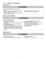
INTRODUCTION » HARDWARE INVENTORY + ADDITIONAL ITEMS FOR PURCHASE + TOOLS NEEDED HARDWARE INVENTORY NOTE: Hardware quantities shown below are for LA412. Quantities are doubled for LA412-S. Hex Nut 5/16"-18 (1) Flat Washer 5/16" (1) Keylock Cap Key (2) Lock Washer 3/8" (3) Flat Washer 3/8" (3) Lock Washer 5/16" (1) Hex Bolt 5/16"-18 x 1-1/2" (1) Hex Bolt 3/8"-16 x 1-1/2" (1) Pin (2) Hairpin Clip (2) Hex Nut 3/8"-16 (3) Carriage Bolt 3/8" x 5-15/16" (2) ADDITIONAL ITEMS FOR PURCHASE The following items are REQUIRED to complete the installation: ALL MODELS: HARDWARE • 5/16" mounting hardware for gate bracket. • The following hardware is needed to mount the control box depending on the mounting surface: Wood: Four #8 1-1/4" zinc plated wood screws. Metal: Four #10-32x6" zinc plated machine screws with nut and lock washers. Concrete, Brick, etc.: Four 1/4" x 1-3/4" masonry screws. Post: U-bolt size will vary depending on post. The U-bolt thread sizes for the control boxes are: 1/4" - standard control box 3/8" - XLM control box PHOTOELECTRIC SENSORS The Model 50-220 photoelectric sensors are intended for installation with the operators covered in this manual. To order call 1-800-528-2806 or visit www.liftmaster.com. LA412-S ONLY: CONDUIT UL Listed outdoor electrical conduit with 3/4" diameter to hold the extension cable between the junction box and the control box. TOOLS NEEDED During assembly, installation and adjustment of the operator, instructions will call for tools as illustrated below. Deep Well Sockets and Wrench 1/2", 5/8", 7/16", 9/16" and 1/4" Carpenter's Level Screwdriver Drill Adjustable End Wrench Drill Bits 1/2", 3/16", 5/16" and 5/32" Clamps 12 Pencil Tape Measure Hammer Phillips Head Screwdriver 7 Wire Strippers (Optional) Welder (Optional) Wire Cutters (Optional)
-
 1
1 -
2
-
 3
3 -
 4
4 -
 5
5 -
 6
6 -
 7
7 -
 8
8 -
 9
9 -
 10
10 -
 11
11 -
 12
12 -
 13
13 -
14
-
15
-
16
-
17
-
18
-
19
-
20
-
21
-
22
-
23
-
24
-
25
-
26
-
27
-
28
-
29
-
30
-
31
-
32
-
33
-
34
-
35
-
36
-
37
-
38
-
39
-
40
-
41
-
42
-
43
-
44
 |
 |
