LiftMaster MTF Installation Manual
LiftMaster MTF Manual
 |
View all LiftMaster MTF manuals
Add to My Manuals
Save this manual to your list of manuals |
LiftMaster MTF manual content summary:
- LiftMaster MTF | Installation Manual - Page 1
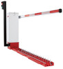
MATTS MOTORIZED TRAFFIC CONTROL DC BARRIER GATE OPERATOR MTS - SURFACE MOUNT MTF - FLUSH MOUNT IN-GROUND INSTALLATION MANUAL RREINCACELDUIIVDOEEDR • THIS PRODUCT IS TO BE INSTALLED AND SERVICED BY A TRAINED GATE SYSTEMS TECHNICIAN ONLY. IMPORTANT: Read and understand Warranty Page first. Batteries - LiftMaster MTF | Installation Manual - Page 2
Instructions 22 9 Sequence Access Management System (SAMS) with "Memory" 23 9 Control Board Layout and Input Locations 24 WIRING 10-13 TROUBLESHOOTING read and fully understand this manual and follow all safety instructions. • DO NOT attempt repair or service of your commercial door and gate - LiftMaster MTF | Installation Manual - Page 3
system) intended for use in a industrial location or building such as a factory or loading dock area or other location not intended to service the general public. CLASS IV - RESTRICTED ACCESS VEHICULAR GATE OPERATOR IV A vehicular gate operator (or system) intended for use in a guarded industrial - LiftMaster MTF | Installation Manual - Page 4
Exposed Rollers • Vertical Posts • Photoelectric Sensors • Instructional and Precautionary Signage 4. Install the gate operator only when For a gate operator utilizing a non-contact sensor: a. Reference owner's manual regarding placement of non-contact sensor for each type of application. b. - LiftMaster MTF | Installation Manual - Page 5
of wrong-way traffic, and a multitude of other malfunctions. LiftMaster will not be responsible for property, vehicles, tires, or personal Sign. Be sure your customer is aware of these inherent dangers. GENERAL INSTRUCTIONS • The traffic system must be installed on a solid surface asphalt or - LiftMaster MTF | Installation Manual - Page 6
SPECIFICATIONS FEATURES • Full service controller with eight . • LED diagnostics for easy troubleshooting. • Adjustable Timer-To-Close • 9/16" Socket for Top Plate • 7/16" Socket for Guide Roller • 9/16" Wrench for 3/8" Anchors • 4.5 mm Allen Wrench /MTF 3-1/2" 13-1/2" FRONT VIEW 14-1/4" 42" 13-1/2" - LiftMaster MTF | Installation Manual - Page 7
must be UL approved. FOR SURFACE MOUNTED SYSTEMS LiftMaster Traffic Control Systems can be surface mounted using position, the closest part of the gate arm and support shall have a lateral offset of at least 2 feet 2. Place your anchors per manufacturer's instructions. Do not use an anchor that - LiftMaster MTF | Installation Manual - Page 8
an open position, the closest part of the gate arm and support shall have a lateral offset of at least 2 feet (61 installed. 3. Partially fill with crushed rock and position the cement blocks as a base to support the top plate of the traffic controller unit level, flush Crushed Rock 12" (30.5 cm - LiftMaster MTF | Installation Manual - Page 9
INSTALLATION ATTACH THE OPERATOR TO THE BASE 1. Position the operator and secure to the base using the included hardware. INSTALL THE BARRIER ARM 1. Line up the holes in the barrier arm with the slotted holes in gate arm bracket. 2. Insert the bolts through the barrier arm and gate arm bracket. 3. - LiftMaster MTF | Installation Manual - Page 10
and secured, at that time the operator may be returned to service. • Disconnect power at the fuse box BEFORE proceeding. Operator MUST larger) 600 volt insulated wire only. NOTE: Do not connect the batteries until instructed. 120 VAC 1. Ensure your main power is OFF before connecting the AC power. - LiftMaster MTF | Installation Manual - Page 11
above inputs. C18 U18 C15 F NOTE: Above inputs are tied to LED indicators to show input command activity. J5 Wiring Inputs on the control board MANUAL 1 2 3 4 5 6 7 8 9 1Ø 11 12 OPEN Q2 J5 S3 CLOSE R21 3 D15 D16 D17 D18 D19 D22 D23 D24 T2 T1 OPEN 1 OPEN 2 T4 T3 OPEN 3 AUX 4 R24 - LiftMaster MTF | Installation Manual - Page 12
+ each battery if one is not already in place. IMPORTANT: Do not run operator without installing the batteries. Replace batteries in pairs using LiftMaster 29-NP712 batteries. Failure to install batteries correctly will cause damage and will not be covered by warranty. Black Lead Jumper Red Lead - LiftMaster MTF | Installation Manual - Page 13
WIRING PRIMARY/SECOND WIRING 1. In a primary/second configuration, either operator can be the primary. 2. Choose an operator to be the primary and then direct all control wiring to it (also install vehicle detectors and receivers in it). 3. At the primary, any input (at J5) with control wires ( - LiftMaster MTF | Installation Manual - Page 14
in SERIOUS INJURY or DEATH to persons trapped beneath the door. WIRING Refer to your commercial door operator or gate operator owner manual or wiring diagrams for specific wiring information. LEDs SINGLE CHANNEL Receiver Single Operator(s) CH1 CH3 CH2 INSTALLATION The receiver and antenna - LiftMaster MTF | Installation Manual - Page 15
commercial door operator or gate operator wiring diagrams for instructions on connecting two or more 3-Button control devices. PROGRAMMING . adjustment or modifications of this receiver are prohibited. THERE ARE NO USER SERVICEABLE PARTS. This device complies with Part 15 of the FCC rules and IC - LiftMaster MTF | Installation Manual - Page 16
FEATURES AND FUNCTIONS S1 DIP SWITCHES A S1 Dip Switch Block BC DE 1 1 J2 AUX LIMITS M/S 2 D14 F3 R13 U19 J4 BAT- MOV MOTOR J 1 ACC+ ACC- BAT- BAT+ 24VAC XFMR MOTOR R Blue Orange D8 D1Ø 1. Disconnect power to the operator. S1 S2 1 2345678 1 2345678 2. For left-hand - LiftMaster MTF | Installation Manual - Page 17
FEATURES AND FUNCTIONS S2 DIP SWITCHES S2 Dip Switch Block F G HI 1 J2 1 J AUX LIMITS M/S R1 D8 D1Ø S1 S2 1 2345678 1 2345678 R1 R12 U4 F TIMER-TO-CLOSE DIP Switch S2-1 to S2-5 The S2-1 to S2-5 DIP switches will set the period of time the gate remains opened after reaching the - LiftMaster MTF | Installation Manual - Page 18
FOLLOW ALL INSTRUCTIONS. 5. Use the emergency release ONLY when the gate is not moving. 2. NEVER let children operate or play with gate controls. Keep the remote control away from children. 6. KEEP GATES PROPERLY MAINTAINED. Read the owner's manual. Have a qualified service person make repairs - LiftMaster MTF | Installation Manual - Page 19
and remove all power to the 8. Loosen the hardware that holds the guide roller assembly under the gate opener. NOTE: Ensure that batteries are also the tray, and tighten the bolts. service side, if the gate arm extends to the left, the left turnbuckle 9. Manually spin the MAT pulley to close the - LiftMaster MTF | Installation Manual - Page 20
◆ z Repeat ALL procedures. GENERAL SERVICE • If the belt is loose or needs replacement, adjust with 4 bolts that support motor to allow 1/4" play. • Battery Test Description section for manually initiating the battery test. BATTERY HANDLING / STORAGE LiftMaster does not recommend storage - LiftMaster MTF | Installation Manual - Page 21
ADDITIONAL FEATURES SUGGESTED LOOP SENSOR LOCATIONS Do not allow control devices to be within 10 feet of gate or operator. RECOMMENDATIONS: • If vehicle detectors are used to open or close the gate, use of the presence contacts are recommended. Using the pulse contacts will Close Loop REDUCE - LiftMaster MTF | Installation Manual - Page 22
ADDITIONAL FEATURES TRAP INSTRUCTIONS INSTALL THE K1 AUXILIARY RELAY AND CONNECTOR AT MATTS CONNECTED TO THE ACCESS DEVICE 1. Press the relay into the K1 location ensuring the pins are - LiftMaster MTF | Installation Manual - Page 23
ADDITIONAL FEATURES SEQUENCE ACCESS MANAGEMENT SYSTEM (SAMS) WITH "MEMORY" SAMS WITH OTHER OPERATORS Requires the K1 Relay Option (Order SAMS Kit) This feature allows a logical interface between the MATTS barrier gate and a swing, slide, etc. gate operator (or MTC-31). All that is required is 4 - LiftMaster MTF | Installation Manual - Page 24
are running properly. D12: Battery status. See diagnostic procedures. D14: AC power indicator. Shows that AC power is present. S3: Manual open. To allow gate to be opened or closed during service of operator. F3: 10 amp ATO type fuse for 24 Vac input power. (UL listed fuse only.) F4: 15 amp - LiftMaster MTF | Installation Manual - Page 25
TROUBLESHOOTING WARNING - DISCONNECT BATTERIES AND AC POWER BEFORE SERVICING ANY MECHANICAL OR MOVING COMPONENTS. BATTERY CHECKOUT When the batteries become weak the gate will begin to run noticeably slower. NOTE: Batteries should only be - LiftMaster MTF | Installation Manual - Page 26
kit K99-ENF-DRCHN Drive chain kit K99-ENF-BRNGKT Bearing kit PARTS SHIPPED ITEM MATTS Operator Controller Operator Cover Installation and Service Manual Arm Bolts with Washers Nylon Nuts 7AH Batteries MATTS TOWER UNIQUE PARTS LIST QTY ITEM PART NUMBER DESCRIPTION 1 * MA020T Operator Cover - LiftMaster MTF | Installation Manual - Page 27
following remote controls are compatible with operators manufactured by LiftMaster after 1993. Contact your authorized LiftMaster dealer for additional details and options. 3-BUTTON REMOTE , wire jumper, duplex box covers and detailed instructions. SAMSKIT Includes required relay and limits. 27 - LiftMaster MTF | Installation Manual - Page 28
final determination as to the existence and causes of any defect or failure. Any part or parts found to be defective and are returned to LiftMaster within the warranty period, shall at our option be repaired or replaced free of charge F.O.B. the factory. Freight is not included at any time on - LiftMaster MTF | Installation Manual - Page 29
C. C. MOTORISÉ DE RÉGULATION DE LA CIRCULATION MATTS MTS - MONTAGE SUR SURFACE MTF - MONTAGE AFFLEURANT DANS LE SOL MANUEL D'INSTALLATION COFOMRURAMNDIASIUONNDE • CE PRODUIT DOIT ÊTRE assurer le bon fonctionnement de l'actionneur. Utiliser (2) batteries LiftMaster 7AH de 12 V c. c. (Pièce no MBAT). - LiftMaster MTF | Installation Manual - Page 30
Remplacement de la goupille de cisaillement 20 Batterie 20 CARACTÉRISTIQUES SUPPLÉMENTAIRES 21-24 Emplacements suggérés des boucles de détection 21 Instructions pour la trappe 22 Système de gestion d'accès séquencé avec « mémoire » (SAMS) 23 Disposition de la carte logique et emplacements - LiftMaster MTF | Installation Manual - Page 31
SÉCURITÉ AVERTISSEMENT : Ce produit peut vous exposer à des produits chimiques comme le plomb, reconnu par l'État de la Californie comme cause de cancers, d'anomalies congénitales et d'autres problèmes liés à la reproduction. Pour plus d'informations, visitez www.P65Warnings.ca.gov CLASSIFICATIONS - LiftMaster MTF | Installation Manual - Page 32
en vue, une de chaque côté de la barrière. 11. Pour un actionneur de barrière utilisant un capteur sans contact : a. Consulter le manuel d'instructions concernant l'emplacement du capteur sans contact pour chaque type d'application. b. Des précautions doivent être prises pour réduire le risque de - LiftMaster MTF | Installation Manual - Page 33
dans la mauvaise direction, et une multitude d'autres dysfonctionnements. LiftMaster ne sera pas tenue responsable des dommages matériels, votre client a été mis au courant de ces dangers inhérents au système. INSTRUCTIONS GÉNÉRALES • Le système de régulation de la circulation doit être installé sur - LiftMaster MTF | Installation Manual - Page 34
ÉRISTIQUES • Contrôleur de service complet avec huit entrées pour la plaque supérieure • Douille de 7/16 po pour le galet du guide • Clé de 9/16 po pour les ancrages de 3/8 po • Cl qui n'a jamais besoin d'être ciré ou peint (exclut les tours). MTS/MTF 34,29 cm (13 1/2 po) 8,89 cm (3 1/2 po) VUE - LiftMaster MTF | Installation Manual - Page 35
prêt à être mis en service. ACHEMINER LE CONDUIT Consulter les codes èmes de régulation de la circulation LiftMaster peuvent être installés selon l'une du bras de la barrière et du support la plus proche de la face de la 2. Placer les ancrages selon les instructions du fabricant. Ne pas utiliser - LiftMaster MTF | Installation Manual - Page 36
moins 61 cm (2 pi) entre la partie du bras de la barrière et du support la plus proche de la face de la bordure de la trajectoire de course de la po) 40,6 cm (16 po) positionner les blocs de béton comme base pour supporter la plaque supérieure de l'unité du contrôleur de circulation de manière - LiftMaster MTF | Installation Manual - Page 37
la quincaillerie fournie. INSTALLER LE BRAS DE LA BARRIÈRE 1. Aligner les orifices dans le bras de la barrière sur les fentes dans le support du bras de la barrière. 2. Insérer les boulons par le bras de la barrière et le - LiftMaster MTF | Installation Manual - Page 38
ée; ce n'est qu'à ce moment que l'actionneur peut être remis en service. • Déconnecter l'alimentation au niveau de la boîte à fusibles AVANT ) de 600 V homologué UL. REMARQUE : Ne pas connecter les batteries jusqu'à instruction de le faire 120 V C. A. 1. S'assurer que l'alimentation principale a été - LiftMaster MTF | Installation Manual - Page 39
-dessus sont liées aux témoins à DEL pour montrer l'activité de commande d'entrée. Entrées de câblage J5 sur la carte logique C18 U18 C15 F MANUAL 1 2 3 4 5 6 7 8 9 1Ø 11 12 OPEN Q2 J5 S3 CLOSE R21 3 D15 D16 D17 D18 D19 D22 D23 D24 T2 T1 OPEN 1 OPEN 2 T4 T3 OPEN 3 AUX 4 R24 - LiftMaster MTF | Installation Manual - Page 40
IMPORTANT: Ne pas faire fonctionner l'actionneur sans d'abord installer les batteries. Remplacer les batteries en paires en utilisant des batteries LiftMaster 29-NP712. Le manquement à installer correctement les batteries causera des dommages qui ne seront pas couverts par la garantie. - Batterie - LiftMaster MTF | Installation Manual - Page 41
CÂBLAGE CÂBLAGE PRIMAIRE/SECONDAIRE 1. Dans une configuration primaire/secondaire, l'un des deux actionneurs peut être désigné comme actionneur primaire. 2. Choisir un actionneur primaire, puis y diriger tout le câblage de commande (y installer aussi les détecteurs de véhicule et les récepteurs). - LiftMaster MTF | Installation Manual - Page 42
INSTALLER LE RÉCEPTEUR APPLICATION Le récepteur peut être utilisé comme récepteur à un ou trois canaux pour commander jusqu'à 3 actionneurs commerciaux de barrière ou de porte. Le récepteur peut aussi être utilisé avec une télécommande à trois boutons pour activer les fonctions d'OUVERTURE, de - LiftMaster MTF | Installation Manual - Page 43
Dispositif de commande à 3 boutons Consulter les schémas de câblage de votre actionneur commercial de porte ou de barrière pour des instructions sur la façon de connecter plus de deux dispositifs de commande à trois boutons. PROGRAMMATION PROGRAMMER UNE TÉLÉCOMMANDE À UN SEUL BOUTON 1 Enfoncer - LiftMaster MTF | Installation Manual - Page 44
CARACTÉRISTIQUES ET FONCTIONS COMMUTATEURS DIP S1 A Bloc de commutateurs DIP S1 BC DE 1 1 J2 AUX LIMITS M/S D12 D14 F3 R13 U19 J4 BAT- MOV MOTOR J 1 ACC+ ACC- BAT- BAT+ 24VAC XFMR MOTOR R Bleue Orange D8 D1Ø 1. Déconnecter l'alimentation à l'actionneur. S1 S2 1 2345678 - LiftMaster MTF | Installation Manual - Page 45
CARACTÉRISTIQUES ET FONCTIONS COMMUTATEURS DIP S2 Bloc de commutateurs DIP S2 F G HI 1 J2 1 J AUX LIMITS M/S R1 D8 D1Ø S1 S2 1 2345678 1 2345678 R1 R12 U4 F MINUTERIE DE FERMETURE Commutateur DIP S1-1 à S1-5 Les commutateurs S2-1 à S2-5 permettent de régler la durée pendant - LiftMaster MTF | Installation Manual - Page 46
ère n'est pas en mouvement. 6. GARDER LES BARRIÈRES BIEN ENTRETENUES.Lire le manuel d'instructions. Faire réparer la barrière par un technicien compétent. 3. GARDER TOUJOURS les personnes et TOUT entretien IMPÉRATIF être effectué par un professionnel LiftMaster. 10. CONSERVER CES INSTRUCTIONS. 18 - LiftMaster MTF | Installation Manual - Page 47
du galet-guide couper toute alimentation à l'actionneur. REMARQUE : S'assurer que sous la découpe centrale du bac support de batterie. pas sur le bac support et 2. Positionner l'assemblage du tendeur par-dessus la poulie serrer les boulons. d'entraînement supérieure. Du côté service, si le bras - LiftMaster MTF | Installation Manual - Page 48
(de solides coups sont plus efficaces que de petits coups légers). 5. Réinstaller le support de bras de la barrière. 6. Graisser légèrement la nouvelle goupille et l'ins Remplacer les batteries en paires en utilisant des batteries LiftMaster 29-NP712. Le manquement à installer correctement les - LiftMaster MTF | Installation Manual - Page 49
CARACTÉRISTIQUES SUPPLÉMENTAIRES EMPLACEMENTS SUGGÉRÉS DES BOUCLES DE DÉTECTION Ne pas placer des dispositifs de commande à moins de 3 m (10 pi) de la barrière ou de l'actionneur. RECOMMANDATIONS: • Si des détecteurs de véhicule sont utilisés pour ouvrir ou fermer la barrière, l'utilisation de - LiftMaster MTF | Installation Manual - Page 50
CARACTÉRISTIQUES SUPPLÉMENTAIRES INSTRUCTIONS POUR LA TRAPPE INSTALLER LE RELAIS AUXILIAIRE K1 ET LE CONNECTEUR AU MATTS CONNECTÉ AU DISPOSITIF D'ACCÈS 1. Enfoncer le relais à l'emplacement K1 pour s'assurer que - LiftMaster MTF | Installation Manual - Page 51
CARACTÉRISTIQUES SUPPLÉMENTAIRES SYSTÈME DE GESTION D'ACCÈS SÉQUENCÉ AVEC « MÉMOIRE » SYSTÈME DE GESTION D'ACCÈS SÉQUENCÉ (SAMS) AVEC D'AUTRES ACTIONNEURS Exige l'option de relais K1 (Commander la trousse SAMS) Cette fonction permet une interface logique entre la barrière MATTS et un actionneur de - LiftMaster MTF | Installation Manual - Page 52
que l'alimentation c. a. est présente. S3 : Ouverture manuelle. Pour permettre à la barrière d'être ouverte ou fermée pendant que l'actionneur est en service. F3 : Fusible de 10 A de type ATO pour une alimentation d'arrivée de 24 V c. a. (Fusible homologué UL uniquement.) F4 : Fusible de 15 A de - LiftMaster MTF | Installation Manual - Page 53
DÉPANNAGE AVERTISSEMENT- DÉCONNECTER LES BATTERIES ET L'ALIMENTATION C. A. AVANT TOUTE INTERVENTION SUR TOUT COMPOSANT MÉCANIQUE OU MOBILE. VÉRIFICATION DE LA BATTERIE Lorsque les batteries sont sur le point d'être épuisées, la barrière commencera à fonctionner de manière plus lente. REMARQUE :Les - LiftMaster MTF | Installation Manual - Page 54
Démultiplicateur (60:1) 6 MA006 Châssis en aluminium 7 MA007 Courroie d'entraînement 8 MA008 Poulie du démultiplicateur 9 MA009 Poulie du moteur 10 MA010 Support de bras de barrière 11 MA011 Aimant 12 MA012 Bras de came 13 MA013 Goupille de cisaillement 14 MA014 Boulon et - LiftMaster MTF | Installation Manual - Page 55
Les télécommandes suivantes sont compatibles avec les actionneurs fabriqués par LiftMaster après 1993. Contacter votre détaillant autorisé LiftMaster pour plus de détails et d'options. TÉLÉCOMMANDE À TROIS BOUTONS le fil de liaison, les couvercles de boîte double et des instructions détaillées. 27 - LiftMaster MTF | Installation Manual - Page 56
batteries, les dommages au support du bras et/ou au SERVICE DE L'ACTIONNEUR CONFIRME QUE L'UTILISATEUR ACCEPTE DE MANIÈRE INCONDITIONNELLE TOUTES LES DISPOSITIONS CI-DESSUS. Les matériaux, composants, caractéristiques générales et techniques peuvent être modifiées sans préavis. 01-39071 LiftMaster
-
 1
1 -
 2
2 -
 3
3 -
 4
4 -
 5
5 -
 6
6 -
 7
7 -
8
-
9
-
10
-
11
-
12
-
13
-
14
-
15
-
16
-
17
-
18
-
19
-
20
-
21
-
22
-
23
-
24
-
25
-
26
-
27
-
28
-
29
-
30
-
31
-
32
-
33
-
34
-
35
-
36
-
37
-
38
-
39
-
40
-
41
-
42
-
43
-
44
-
45
-
46
-
47
-
48
-
49
-
50
-
51
-
52
-
53
-
54
-
55
-
56
 |
 |

MATTS MOTORIZED TRAFFIC CONTROL
DC BARRIER GATE OPERATOR
MTS – SURFACE MOUNT
MTF – FLUSH MOUNT IN-GROUND
INSTALLATION MANUAL
RADIO
RECEIVER
INCLUDED
IMPORTANT:
Read and understand Warranty Page first. Batteries (included) MUST be connected for proper operation of operator. Use (2)
LiftMaster 12 Vdc 7AH (Part # MBAT).
•
THIS PRODUCT IS TO BE INSTALLED AND
SERVICED BY A TRAINED GATE SYSTEMS
TECHNICIAN ONLY.