LiftMaster MTF Installation Manual - Page 19
Install The Drive Chain, Install The Traffic Light
 |
View all LiftMaster MTF manuals
Add to My Manuals
Save this manual to your list of manuals |
Page 19 highlights
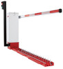
INSTALL THE DRIVE CHAIN 1. Leave the gate opener on the open limit and remove all power to the 8. Loosen the hardware that holds the guide roller assembly under the gate opener. NOTE: Ensure that batteries are also disconnected. center battery tray cutout. Adjust the rollers to ensure that the chain 2. Position the turnbuckle assembly over top drive sprocket.From the does not rub on the tray, and tighten the bolts. service side, if the gate arm extends to the left, the left turnbuckle 9. Manually spin the MAT pulley to close the boom. Verify that spikes should be one link higher than the right. From the service side, if the are in the true vertical position when the boom is lowered. gate arm extends to the right, the right turnbuckle should be one link 10. Reconnect main power and batteries. higher. 11. Test system, adjusting limits as needed. 3. Rotate the threaded shafts so that the thin edge faces you. This allows links in the lift chain to be aligned with the teeth of the lower sprocket. 12. If a traffic light is present, verify proper operation - light is green only when boom is in the full vertical position. The light is red all other times. 4. Route lower lift chain as follows: From the service side, the teeth sections extend to your LEFT: Use supplied master link kit to attach one end of the long chain Gate arm on right to the left side of the turnbuckle assembly. To lower sprocket Route the long chain around the base sprocket from front (closest to you), underneath the sprocket, and to the rear. From the service side, the teeth sections extends to your RIGHT: Use supplied master link kit to attach one end of the long chain to the right side of the turnbuckle assembly. Route the long chain around the base sprocket from front (closest to you), underneath the sprocket, and to the rear. NOTE: For surface mounted units, some of the surface material may need to be removed to prevent the chain from rubbing on the surface. Gate arm on left 5. Attach the remaining end of the lift chain to remaining threaded shaft To lower sprocket using the supplied master link. 6. Note that the threaded shafts will be installed in the turnbuckles at the approximate position for proper chain tension, but minor adjustment may be required. Adjust the chain tension as needed to take up slack. The chain should not droop, but it should be pinched with fingers easily. Too much chain tension will cause unneeded wear and stress on the system. Service Side 7. Check the chain alignment from top to bottom shafts. The chain should be in line and should not angle to either side. The lower sprocket inside the base can be adjusted by loosening the two set screws. The sprocket is keyed to prevent rotation, but can be shifted left or right along the shaft. Limit arm rotational position can be adjusted on the lower shaft with set screw (picture). With boom raised (open) and spikes lowered, rotate the arm containing the magnet until the light turns solid green. Tighten allen/set screws. INSTALL THE TRAFFIC LIGHT 1. Route the power wire through the hole in the base. 2. Position the traffic light on the base and use bolts (provided) to fasten the traffic light to the base. 3. Use the two spade connectors pre-wired in the MAT gate operator to connect to the lighting wiring in the Enforcer base. 24VDC ACC. PWR. (J4 on the DCS main board) + - Orange iControls Traffic Light TL96-LV-BK Red N.C. Reed Switch Black Black LED lights red when switch is closed. Black 8 Black 7 Blue Black 19 6 4 2 5 3 1 175A0318 Socket 160A0191 Relay Black Green
-
 1
1 -
2
-
3
-
4
-
5
-
6
-
7
-
8
-
9
-
10
-
11
-
12
-
13
-
 14
14 -
 15
15 -
 16
16 -
 17
17 -
 18
18 -
 19
19 -
 20
20 -
 21
21 -
 22
22 -
 23
23 -
 24
24 -
25
-
26
-
27
-
28
-
29
-
30
-
31
-
32
-
33
-
34
-
35
-
36
-
37
-
38
-
39
-
40
-
41
-
42
-
43
-
44
-
45
-
46
-
47
-
48
-
49
-
50
-
51
-
52
-
53
-
54
-
55
-
56
 |
 |
