LiftMaster MTF Installation Manual - Page 8
Tools Needed For Flush Mount Installations
 |
View all LiftMaster MTF manuals
Add to My Manuals
Save this manual to your list of manuals |
Page 8 highlights
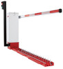
INSTALLATION TOOLS NEEDED FOR FLUSH MOUNT INSTALLATIONS • Excavation and cement mixing equipment: water, shovel, wheelbarrow, flat-trowel Tunnel • 1 yard of 3000 PSI premix cement • Crushed rock • 6 to 18 open web hollow blocks (standard 8 x 8 x 16 CMU's), depending on your preference 1. Carefully determine the location for your Traffic Control Units. Normally, you would want the units placed at least 15' - 20' (4.5m - 6m) into the Cement lane. When gate arms are in the vertical position or rotated to an open position, the closest part of the gate arm and support shall have a lateral offset of at least 2 feet (61 cm) from the face of the curb or the edge of the traveled way. 36" (91.4 cm) 2. Excavate the placement area 24" - 36" (61 cm - 91.4 cm) deep, (depending on drainage needs in your area) by a minimum of 36" (91.4 cm) long and 16" (40.6 cm) wide, per unit installed. 3. Partially fill with crushed rock and position the cement blocks as a base to support the top plate of the traffic controller unit level, flush Crushed Rock 12" (30.5 cm) 24" - 36" (61 cm - 91.4 cm) 16" (40.6 cm) with the pavement surface, to allow for proper drainage. This placement area will be 24" (61 cm) inches deep by a minimum of 28" (71 cm) long and 26" (66 cm) wide. Partially fill with crushed rock to a depth of 12" (30.5 cm). IMPORTANT: Locate power source conduit if it is to be below the ground, before pouring concrete. TIP: To keep the controller unit level with the surface during installation, bolt two flat steel bars, approximately 24" (61 cm) long, perpendicular to the unit to the top plate at either end, creating leveling-handles. Prepare the steel bars by drilling holes to match a pair of bolt holes in the top plate. Bolt the bars perpendicular to the top plate using the existing pairs of bolts approximately 18" (45.7 cm) from each end of the unit. This creates temporary handles and flaps that will keep the controller unit level with the existing pavement while the cement cures. 4. Pour cement around the outside unit to set it in place, fill the excavation and even the pavement surface. Do not pour cement into the inside of the traffic system, pour only around the perimeter. 5. After the cement has set and cured, unbolt the leveling-handles and replace the bolts in the top plate. Normal traffic may proceed over the controller. 6. With the tooth section located so that the coupling shaft will connect with the opposite connection shaft, slide the entire tooth section so that it is flush against the operator. 7. Repeat the alignment and connection process for any and all remaining tooth sections, bolting or using epoxy to fasten each section once the sections are all connected. Tighten all hex head screws so each tooth section is attached to the next tooth section and the tunnel shaft. 8. Reinstall the top plates of the teeth sections and the operator tunnel. 8
-
 1
1 -
2
-
 3
3 -
 4
4 -
 5
5 -
 6
6 -
 7
7 -
 8
8 -
 9
9 -
 10
10 -
 11
11 -
 12
12 -
 13
13 -
14
-
15
-
16
-
17
-
18
-
19
-
20
-
21
-
22
-
23
-
24
-
25
-
26
-
27
-
28
-
29
-
30
-
31
-
32
-
33
-
34
-
35
-
36
-
37
-
38
-
39
-
40
-
41
-
42
-
43
-
44
-
45
-
46
-
47
-
48
-
49
-
50
-
51
-
52
-
53
-
54
-
55
-
56
 |
 |
