LiftMaster MTF Installation Manual - Page 7
Installation
 |
View all LiftMaster MTF manuals
Add to My Manuals
Save this manual to your list of manuals |
Page 7 highlights
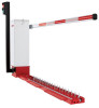
INSTALLATION INSTALL THE MOTORIZED TRAFFIC CONTROL BASE AND EXTENSIONS Place adequate warning barricades in the traffic lane to divert traffic during the construction process and until ready to activate. ROUTE THE CONDUIT Check the national and local building codes before installation. The conduits should be installed to fit the 3-1/2" x 3-1/2" (8.9 cm x 8.9 cm) opening in the pedestal base plate or the 10-1/4" x 8-1/4" (26 cm x 21 cm) opening in the tower base plate. Install conduits for the 120/230 Vac main power, low voltage control wiring, and one or two extra for loop sensor leads. Conduit size should be limited to 1/2" (1.3 cm) when possible to reduce crowding if more than four are needed. All conduits must be UL approved. FOR SURFACE MOUNTED SYSTEMS LiftMaster Traffic Control Systems can be surface mounted using one of two methods of application or a combination of the two. • The first is by bolting the units down to a concrete surface (not recommended for asphalt). • The second is by affixing them to the road surface using epoxy in the case of asphalt (tarmac) road surfaces. 1. Carefully determine the location for your Traffic Control Units. Normally you would want the units placed at least 15' - 20' (4.5m - 6m) into the lane. When gate arms are in the vertical position or rotated to an open position, the closest part of the gate arm and support shall have a lateral offset of at least 2 feet (61 cm) from the face of the curb or the edge of the traveled way. 2. Clean the area with a weed blower, broom or other method to ensure a clean and dry surface. 3. Mark the location with a chalk line or other suitable mark to assist in aligning and locating the units in the desired position. You may also place the individual segments in the location you wish to install them and then mark the location. Make sure the teeth are oriented the correct way. 4. Lay out all components of the traffic controller (operator, tunnel assembly, teeth and top plate assembly, and end bevel) as they will be when installed. Standard execution is to locate the operator on the left side of the traffic lane. Some applications may require a right handed system where the operator is located on the right side of the traffic lane. 5. Check to make sure there are no obstructions in the traffic lane and check for proper traffic flow angles. Traffic controllers must not be installed on any curves, slopes, grades or anywhere that immediate turns are required before or after the units. 6. Set operator and tunnel, teeth sections, and end bevel in desired location. Bolt the operator and tunnel section down. 7. Remove the top plates or the tunnel and teeth sections. 8. The coupling joins the shafts between sections, providing positive drive and assuring proper tooth alignment. Align the adjoining shafts and fasten together with coupler. 9. With the tooth section located so the shaft can slide into the coupling, slide the entire tooth section so it is flush against the operator tunnel. 10. Bolt the tunnel and tooth section together. 11. Bolt the first tooth section. 12. Remove coupler, if present, from the last tooth section. Place the end bevel at the end of the last tooth section. Bolt it to the adjacent tooth section and then bolt it down. BOLTING TO CONCRETE SURFACE ONLY 1. When bolting into concrete (not recommended for asphalt) drill holes in the road surface in the corresponding larger hole on each spike section. 2. Place your anchors per manufacturer's instructions. Do not use an anchor that will stick up above the traffic control unit that could cause damage to the passing tires. The recommended product is a 3/8" large diameter concrete anchor. 3. If additional holding force is desired, add epoxy as mentioned on the following page. Tunnel 3/8" Concrete Anchor Epoxy area 7 Tooth section End bevel
-
 1
1 -
 2
2 -
 3
3 -
 4
4 -
 5
5 -
 6
6 -
 7
7 -
 8
8 -
 9
9 -
 10
10 -
 11
11 -
 12
12 -
13
-
14
-
15
-
16
-
17
-
18
-
19
-
20
-
21
-
22
-
23
-
24
-
25
-
26
-
27
-
28
-
29
-
30
-
31
-
32
-
33
-
34
-
35
-
36
-
37
-
38
-
39
-
40
-
41
-
42
-
43
-
44
-
45
-
46
-
47
-
48
-
49
-
50
-
51
-
52
-
53
-
54
-
55
-
56
 |
 |
