LiftMaster MTF Installation Manual - Page 20
Operation And Maintenance
 |
View all LiftMaster MTF manuals
Add to My Manuals
Save this manual to your list of manuals |
Page 20 highlights
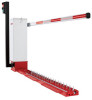
OPERATION AND MAINTENANCE To avoid SERIOUS PERSONAL INJURY or DEATH from electrocution, disconnect ALL electric power BEFORE performing ANY maintenance. Check at the intervals listed in the following chart: ITEM Fasteners Bearings and Shafts Battery Maintenance PROCEDURE Check and tighten as required Check for wear and lubricate Replace batteries. EVERY 3 MONTHS EVERY 6 MONTHS EVERY 12 MONTHS EVERY 24 MONTHS z ◆ z ◆ ◆ z Repeat ALL procedures. GENERAL SERVICE • If the belt is loose or needs replacement, adjust with 4 bolts that support motor to allow 1/4" play. • Battery voltage should be 27.5 +0.05, -0 Vdc disconnected (set with R63, shown on the Control Board Layout page). SHEAR PIN REPLACEMENT If gate arm is vandalized and the tapered pin in the output shaft has been sheared, it must be replaced correctly and with the right pin type. Replacement must be done by always punching out the pin (or pieces) from the small end only. If drilling is required, DO NOT DAMAGE THE SHAFT, use a drill bit smaller than the small hole size of the pin. (Correct pin (P/N MA013) is a 2" pin with a number 6 taper only.) NEVER USE A BOLT AS A TEMPORARY FIX, THIS WILL DAMAGE THE SHAFT AND COLLAR. 1. Turn the S3 Manual Open switch to OPEN on the control board to rotate gate arm bracket to the up position. 2. Disconnect AC power and disconnect batteries. 3. Remove the gate arm bracket and pieces in collar. 4. Drive out pin pieces with hammer and punch (Solid sharp blows are better than light ones). 5. Reinstall gate arm bracket. 6. Lightly oil the new pin and insert into collar. 7. Fully seat pin in shaft by tapping on large end. 8. Reinstall the barrier arm if required. 9. Connect AC power and batteries. 10. Turn off S3 Manual Open switch to CLOSE to put gate into operation. Shear Pin Collar (Operator) Gate Arm Bracket Barrier Arm BATTERY BATTERY DISPOSAL Replaced batteries must be treated as a hazardous waste and disposed of in accordance with State, Local, and Federal Regulations. BATTERY REPLACEMENT Replace batteries in pairs using LiftMaster 29-NP712 batteries. Failure to install batteries correctly will cause damage and will not be covered by warranty. BATTERY MAINTENANCE / TESTING The batteries are maintenance free. However, to ensure proper and safe operation, it is recommended that the batteries be replaced every two years. Battery testing is conducted automatically. See the Battery Test Description section for manually initiating the battery test. BATTERY HANDLING / STORAGE LiftMaster does not recommend storage of batteries in the field. Batteries are intended for immediate use. 20
-
 1
1 -
2
-
3
-
4
-
5
-
6
-
7
-
8
-
9
-
10
-
11
-
12
-
13
-
14
-
 15
15 -
 16
16 -
 17
17 -
 18
18 -
 19
19 -
 20
20 -
 21
21 -
 22
22 -
 23
23 -
 24
24 -
 25
25 -
26
-
27
-
28
-
29
-
30
-
31
-
32
-
33
-
34
-
35
-
36
-
37
-
38
-
39
-
40
-
41
-
42
-
43
-
44
-
45
-
46
-
47
-
48
-
49
-
50
-
51
-
52
-
53
-
54
-
55
-
56
 |
 |
