Linksys PLE200 User Guide - Page 4
List of s - powerline
 |
UPC - 745883577880
View all Linksys PLE200 manuals
Add to My Manuals
Save this manual to your list of manuals |
Page 4 highlights
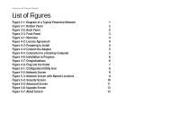
PowerLine AV Ethernet Adapter List of Figures Figure 2-1: Diagram of a Typical Powerline Network 1 Figure 3-1: Bottom Panel 2 Figure 3-2: Back Panel 2 Figure 3-3: Front Panel 3 Figure 4-1: Welcome 4 Figure 4-2: License Agreement 4 Figure 4-3: Preparing to Install 4 Figure 4-4: Connect the Adapter 5 Figure 4-5: Connection to a Desktop Computer 5 Figure 4-6: Installation in Progress 6 Figure 4-7: Congratulations 6 Figure 4-8: Plug into the Outlet 7 Figure 5-1: Configuration Utility Icon 8 Figure 5-2: Network Screen 9 Figure 5-3: Network Screen with Named Locations 9 Figure 5-4: Security Screen 10 Figure 5-5: Advanced Screen 11 Figure 5-6: Upgrade Screen 13 Figure 5-7: About Screen 13
-
 1
1 -
 2
2 -
 3
3 -
 4
4 -
 5
5 -
 6
6 -
 7
7 -
 8
8 -
 9
9 -
 10
10 -
11
-
12
-
13
-
14
-
15
-
16
-
17
-
18
-
19
-
20
-
21
-
22
-
23
-
24
-
25
-
26
-
27
-
28
-
29
-
30
-
31
-
32
-
33
-
34
 |
 |

PowerLine AV Ethernet Adapter
List of Figures
Figure 2-1: Diagram of a Typical Powerline Network
1
Figure 3-1: Bottom Panel
2
Figure 3-2: Back Panel
2
Figure 3-3: Front Panel
3
Figure 4-1: Welcome
4
Figure 4-2: License Agreement
4
Figure 4-3: Preparing to Install
4
Figure 4-4: Connect the Adapter
5
Figure 4-5: Connection to a Desktop Computer
5
Figure 4-6: Installation in Progress
6
Figure 4-7: Congratulations
6
Figure 4-8: Plug into the Outlet
7
Figure 5-1: Configuration Utility Icon
8
Figure 5-2: Network Screen
9
Figure 5-3: Network Screen with Named Locations
9
Figure 5-4: Security Screen
10
Figure 5-5: Advanced Screen
11
Figure 5-6: Upgrade Screen
13
Figure 5-7: About Screen
13