Linksys PLTE200 User Guide - Page 8
Product Overview, Print this at 100% size, and cut along the dotted line. - de
 |
UPC - 745883585311
View all Linksys PLTE200 manuals
Add to My Manuals
Save this manual to your list of manuals |
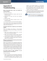
Page 8 highlights
Chapter 2 3. Insert a screw into each hole and leave 3 mm (0.12 inches) of its head exposed. 4. Maneuver the Powerline Adapter so the two wallmount slots line up with the two screws. 5. Place the wall-mount slots over the screws and slide the Powerline Adapter down until the screws fit snugly into the wall-mount slots. 60 mm Wall Mounting Template Print this page at 100% size, and cut along the dotted line. Check the template's accuracy by measuring the distance between the wall-mount slots with a ruler. This distance should be 60 mm. Then place the template on the wall to drill precise spacing. Product Overview Powerline Network Adapter 5
-
 1
1 -
2
-
 3
3 -
 4
4 -
 5
5 -
 6
6 -
 7
7 -
 8
8 -
 9
9 -
 10
10 -
 11
11 -
 12
12 -
 13
13 -
14
-
15
-
16
-
17
-
18
-
19
-
20
-
21
-
22
-
23
-
24
-
25
-
26
-
27
-
28
-
29
-
30
-
31
-
32
-
33
 |
 |

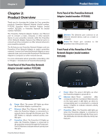
Chapter 2
Product Overview
5
Powerline Network Adapter
Insert a screw into each hole and leave 3 mm
3.
(0.12 inches) of its head exposed.
Maneuver the Powerline Adapter so the two wall-
4.
mount slots line up with the two screws.
Place the wall-mount slots over the screws and slide
5.
the Powerline Adapter down until the screws fit snugly
into the wall-mount slots.
60 mm
Wall Mounting Template
Print this page at 100% size, and cut along the dotted line.
Check the template’s accuracy by measuring the distance
between the wall-mount slots with a ruler. This distance
should be 60 mm. Then place the template on the wall to
drill precise spacing.