MSI 790XT User Guide - Page 40
Adjust PCI-E Frequency MHz
 |
View all MSI 790XT manuals
Add to My Manuals
Save this manual to your list of manuals |
Page 40 highlights
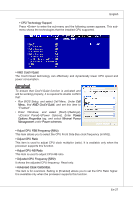
▍ MS-7388 Mainboard ▶ tWTR When the DRAM Timing Mode sets to [DCT 0], [DCT1] or [Both], the field is adjustable. This item controls the Write Data In to Read Command Delay memory timing. This constitutes the minimum number of clock cycles that must occur between the last valid write operation and the next read command to the same internal bank of the DDR device. ▶ tRFC0~3 When the DRAM Timing Mode sets to [DCT 0], [DCT1] or [Both], these fields are adjustable. These settings determine the time RFC take to read from and write to memory cells. ▶ 1T/2T Memory Timing When the DRAM Timing Mode sets to [DCT 0], [DCT1] or [Both], the field is adjustable. This field controls the SDRAM command rate. Selecting [1T] makes SDRAM signal controller to run at 1T (T=clock cycles) rate. Selecting [2T] makes SDRAM signal controller run at 2T rate. ▶ DCT Unganged Mode This feature is used to Integrate two 64-bit DCTs into a 128-bit interface. ▶ FSB/DRAM Ratio This item allows you to select the ratio of FSB/ DRAM. ▶ Adjusted DRAM Frequency (MHz) It shows the adjusted Memory frequency. Read-only. ▶ HT Link Speed This item allows you to set the Hyper-Transport Link speed. Setting to [Auto], the system will detect the HT link speed automatically. ▶ Adjust PCI-E Frequency (MHz) This field allows you to select the PCIE frequency (in MHz). ▶ Auto Disable DRAM/PCI Frequency When set to [Enabled], the system will remove (turn off) clocks from empty DRAM/ PCI slots to minimize the electromagnetic interference (EMI). ▶ CPU Voltage (V)/ DRAM Voltage (V)/ NB Voltage (V)/ HT Link Voltage (V) These items are used to adjust the voltage of CPU, Memory and chipset. ▶ Spread Spectrum When the mainboard's clock generator pulses, the extreme values (spikes) of the pulses create EMI (Electromagnetic Interference). The Spread Spectrum function reduces the EMI generated by modulating the pulses so that the spikes of the pulses are reduced to flatter curves. If you do not have any EMI problem, leave the setting at Disabled for optimal system stability and performance. But if you are plagued by EMI, set to Enabled for EMI reduction. Remember to disable Spread Spectrum if you are overclocking because even a slight jitter can introduce a temporary boost in clock speed which may just cause your overclocked processor to lock up. En-30
-
 1
1 -
2
-
3
-
4
-
5
-
6
-
7
-
8
-
9
-
10
-
11
-
12
-
13
-
14
-
15
-
16
-
17
-
18
-
19
-
20
-
21
-
22
-
23
-
24
-
25
-
26
-
27
-
28
-
29
-
30
-
31
-
32
-
33
-
34
-
 35
35 -
 36
36 -
 37
37 -
 38
38 -
 39
39 -
 40
40 -
 41
41 -
 42
42 -
 43
43 -
 44
44 -
 45
45 -
46
-
47
-
48
-
49
-
50
-
51
-
52
-
53
-
54
-
55
-
56
-
57
-
58
-
59
-
60
-
61
-
62
-
63
-
64
-
65
-
66
-
67
-
68
-
69
-
70
-
71
-
72
-
73
-
74
-
75
-
76
-
77
-
78
-
79
-
80
-
81
-
82
-
83
-
84
-
85
-
86
-
87
-
88
-
89
-
90
-
91
-
92
-
93
-
94
-
95
-
96
-
97
-
98
-
99
-
100
-
101
-
102
-
103
-
104
-
105
-
106
-
107
-
108
-
109
-
110
-
111
-
112
-
113
-
114
-
115
-
116
-
117
-
118
-
119
-
120
-
121
-
122
-
123
-
124
-
125
-
126
-
127
-
128
-
129
-
130
-
131
-
132
-
133
-
134
-
135
-
136
-
137
-
138
 |
 |