MSI 990FXA User Guide - Page 30
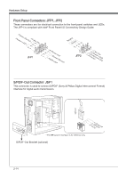
Front Panel Connectors: JFP1, JFP2, S/PDIF-Out Connector: JSP1
 |
View all MSI 990FXA manuals
Add to My Manuals
Save this manual to your list of manuals |
Page 30 highlights
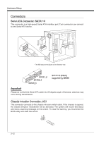
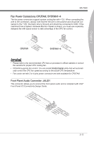
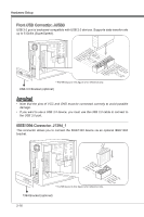
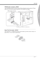
Hardware Setup Front Panel Connectors: JFP1, JFP2 These connectors are for electrical connection to the front panel switches and LEDs. The JFP1 is compliant with Intel® Front Panel I/O Connectivity Design Guide. PowPoewr LeEr DSwi2tc.h+41.0-6..N+8o.-Pin JFP1 1.+3.-5.-7.H+9D.RDReLseEesDrevteSdwitch SpeakeBr2uz.z-e4r.+6.-8.+ JFP2 1.G3.rSo5uu.Psn7opd.NweonedrPLLinEEDD S/PDIF-Out Connector: JSP1 This connector is used to connect S/PDIF (Sony & Philips Digital Interconnect Format) interface for digital audio transmission. 115V 3.V2C.S1C.PGDrIoFund * The MB layout in this figure is for reference only. S/PDIF-Out Bracket (optional) 2-14
-
 1
1 -
2
-
3
-
4
-
5
-
6
-
7
-
8
-
9
-
10
-
11
-
12
-
13
-
14
-
15
-
16
-
17
-
18
-
19
-
20
-
21
-
22
-
23
-
24
-
 25
25 -
 26
26 -
 27
27 -
 28
28 -
 29
29 -
 30
30 -
 31
31 -
 32
32 -
 33
33 -
 34
34 -
 35
35 -
36
-
37
-
38
-
39
-
40
-
41
-
42
-
43
-
44
-
45
-
46
-
47
-
48
-
49
-
50
-
51
-
52
-
53
-
54
-
55
-
56
-
57
-
58
-
59
-
60
-
61
-
62
-
63
-
64
-
65
-
66
-
67
-
68
-
69
-
70
-
71
-
72
-
73
-
74
-
75
-
76
 |
 |
2-14
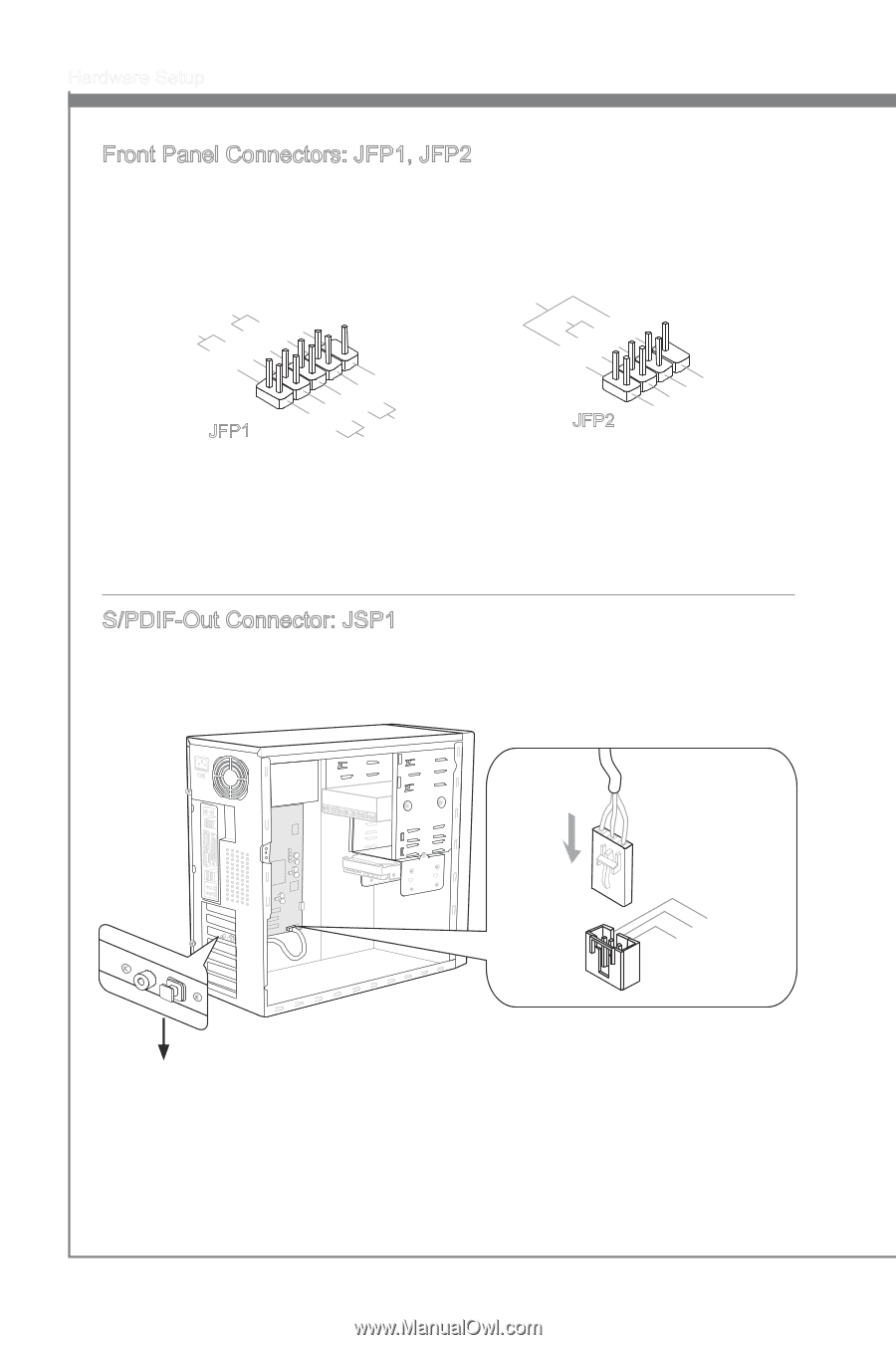
Hardware Setup
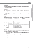
Front Panel Connectors: JFP1, JFP2
These connectors are for electr±cal connect±on to the front panel sw±tches and LEDs.
The JFP1 ±s compl±ant w±th Intel
®
Front Panel I/O Connect±v±ty Des±gn Gu±de.
1.Ground
3.Suspend LED
5.Power LED
7.No Pin
8.+
6.-
4.+
2.-
Buzzer
Speaker
1.+
3.-
10.No Pin
5.-
Reset Switch
HDD LED
Power Switch
Power LED
7.+
9.Reserved
8.-
6.+
4.-
2.+
JFP1
JFP2
S/PDIF-Out Connector: JSP1
Th±s connector ±s used to connect S/PDIF (Sony & Ph±l±ps D±g±tal Interconnect Format)
±nterface for d±g±tal aud±o transm±ss±on.
3.VCC
2.SPDIF
1.Ground
* The MB layout ±n th±s figure ±s for reference only.
S/PDIF-Out Bracket (opt±onal)