MSI G31M3 User Guide - Page 29
IEEE1394 Connector: J1394_1 optional, S/PDIF-Out Connector: JSPD1
 |
View all MSI G31M3 manuals
Add to My Manuals
Save this manual to your list of manuals |
Page 29 highlights
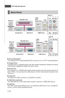
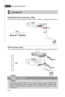
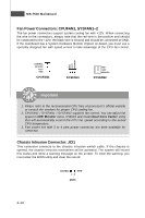
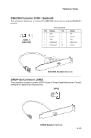
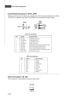
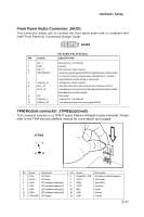
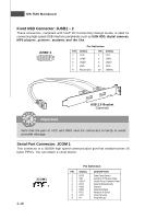
Hardware Setup IEEE1394 Connector: J1394_1 (optional) This connector allows you to connect the IEEE1394 device via an optional IEEE1394 bracket. 9 1 10 2 J1394_1 (optional) Pin Definition PIN SIGNAL PIN 1 TPA+ 2 3 Ground 4 5 TPB+ 6 7 Cable power 8 9 Key (no pin) 10 SIGNAL TPAGround TPBCable power Ground IEEE1394 Bracket (Optional) S/PDIF-Out Connector: JSPD1 This connector is used to connect S/PDIF (Sony & Philips Digital Interconnect Format) interface for digital audio transmission. JSPD1 GND SPDIF VCC S/PDIF Bracket (Optional) 2-15
-
 1
1 -
2
-
3
-
4
-
5
-
6
-
7
-
8
-
9
-
10
-
11
-
12
-
13
-
14
-
15
-
16
-
17
-
18
-
19
-
20
-
21
-
22
-
23
-
 24
24 -
 25
25 -
 26
26 -
 27
27 -
 28
28 -
 29
29 -
 30
30 -
 31
31 -
 32
32 -
 33
33 -
 34
34 -
35
-
36
-
37
-
38
-
39
-
40
-
41
-
42
-
43
-
44
-
45
-
46
-
47
-
48
-
49
-
50
-
51
-
52
-
53
-
54
-
55
-
56
-
57
-
58
-
59
-
60
-
61
-
62
-
63
-
64
-
65
-
66
-
67
-
68
-
69
-
70
-
71
-
72
-
73
-
74
-
75
-
76
-
77
-
78
-
79
-
80
-
81
-
82
-
83
-
84
-
85
-
86
-
87
-
88
-
89
-
90
-
91
 |
 |
2-15
Hardware Setup
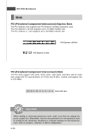
IEEE1394 Connector: J1394_1 (optional)
This connector allows you to connect the IEEE1394 device via an optional IEEE1394
bracket.
Pin Definition
PIN
SIGNAL
PIN
SIGNAL
1
TPA+
2
TPA-
3
Ground
4
Ground
5
TPB+
6
TPB-
7
Cable power
8
Cable power
9
Key (no pin)
10
Ground
J1394_1
(optional)
IEEE1394 Bracket
(Optional)
S/PDIF Bracket
(Optional)
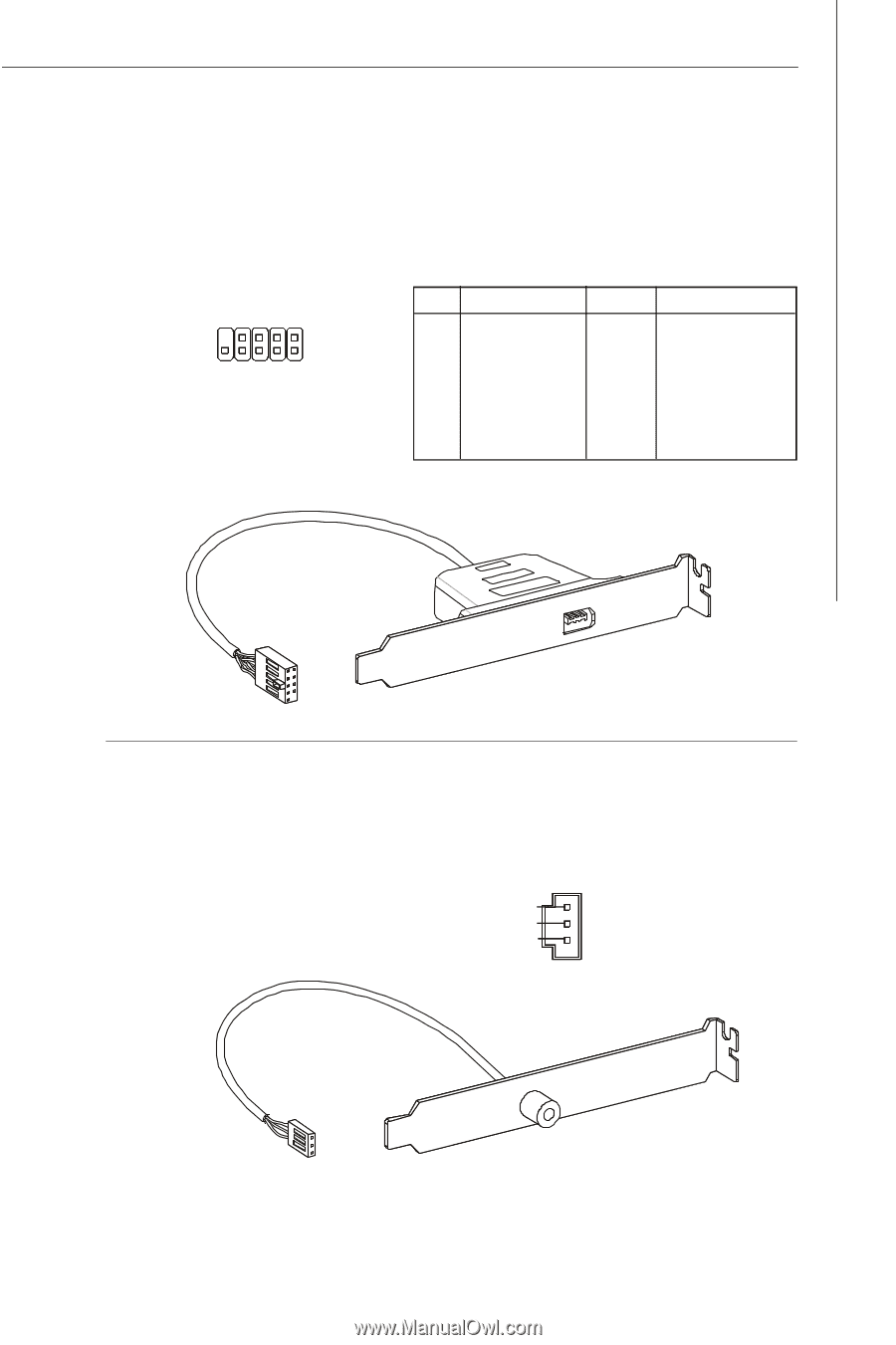
S/PDIF-Out Connector: JSPD1
This connector is used to connect S/PDIF (Sony & Philips Digital Interconnect Format)
interface for digital audio transmission.
JSPD1
1
2
9
10
VCC
SPDIF
GND