MSI G31M3 User Guide - Page 54
Auto Disable DIMM/PCI Frequency - f motherboard
 |
View all MSI G31M3 manuals
Add to My Manuals
Save this manual to your list of manuals |
Page 54 highlights
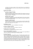
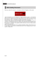
BIOS Setup constitutes the minimum number of clock cycles that must occur between the last valid write operation and the next read command to the same internal bank of the DDR device. Power User M ode Press to enter the sub-menu. ADJUST CHANNEL 0/1 DRIVE These two Groups are used to program RCOMP buffer strengths and slew rate table for the various signal groups of MCH. Each channel contains seven groups of signal ( GROUP 0 ~ GROUP 6) ADJUST ODT Strength This feature is designed to improve the signal integrity of the memory channel. ODT(On-Die termination) allows a DRAM to adjust the termination resistance for each DQ and DQS/DQS# signal. ADJUST SCOMP Strength SCOMP (Secure Communications Processor) hardware protections against DMA devices that allow it to move the corresponding device drivers from the base layer to less critical parts of the system. FSB/Memory Ratio This item will allow you to adjust the FSB/Ratio of the memory. Adjusted DRAM Frequency It shows the adjusted DDR Memory frequency. Read-only. Adjust PCI-E Frequency(MHz) This field allows you to select the PCIE frequency (in MHz). Auto Disable DIMM/PCI Frequency W hen set to [Enabled], the system will remove (turn off) clocks from empty DIMM and PCI slots to minimize the electromagnetic interference (EMI). Spread Spectrum W hen the motherboard's clock generator pulses, the extreme values (spikes) of the pulses create EMI (Electromagnetic Interference). The Spread Spectrum function reduces the EMI generated by modulating the pulses so that the spikes of the pulses are reduced to flatter curves. If you do not have any EMI problem, leave the setting at Disabled for optimal system stability and performance. But if you are plagued by EMI, set to Enabled for EMI reduction. Remember to disable Spread Spectrum if you are overclocking because even a slight jitter can introduce a temporary boost in clock speed which may just cause your overclocked processor to lock up. 3-19
-
 1
1 -
2
-
3
-
4
-
5
-
6
-
7
-
8
-
9
-
10
-
11
-
12
-
13
-
14
-
15
-
16
-
17
-
18
-
19
-
20
-
21
-
22
-
23
-
24
-
25
-
26
-
27
-
28
-
29
-
30
-
31
-
32
-
33
-
34
-
35
-
36
-
37
-
38
-
39
-
40
-
41
-
42
-
43
-
44
-
45
-
46
-
47
-
48
-
 49
49 -
 50
50 -
 51
51 -
 52
52 -
 53
53 -
 54
54 -
 55
55 -
 56
56 -
 57
57 -
 58
58 -
 59
59 -
60
-
61
-
62
-
63
-
64
-
65
-
66
-
67
-
68
-
69
-
70
-
71
-
72
-
73
-
74
-
75
-
76
-
77
-
78
-
79
-
80
-
81
-
82
-
83
-
84
-
85
-
86
-
87
-
88
-
89
-
90
-
91
 |
 |