MSI H87M User Guide - Page 38
Video Demonstration, Important, JFP1, JFP2: System Panel Connectors
 |
View all MSI H87M manuals
Add to My Manuals
Save this manual to your list of manuals |
Page 38 highlights
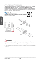
Chapter 1 JFP1, JFP2: System Panel Connectors These connectors connect to the front panel switches and LEDs. The JFP1 connector is compliant with the Intel® Front Panel I/O Connectivity Design Guide. When installing the front panel connectors, please use the optional M-Connector to simplify installation. Plug all the wires from the computer case into the M-Connector and then plug the M-Connector into the motherboard. Video Demonstration Watch the video to learn how to Install front panel connectors. http://youtu.be/DPELIdVNZUI SpeakeBr2uz.z-e4r.+6.-8.+ JFP2 PowPoewr LeEr DSwi2tc.h+41.0-6..N+8o.-Pin 1.G3.rSo5uu.Psn7opd.NweonedrPLLinEEDD JFP1 1.+3.-5.-7.H+9D.RDReLseEesDrevteSdwitch Important • On the connectors coming from the case, pins marked by small triangles are positive wires. Please use the diagrams above and the writing on the optional MConnectors to determine correct connector orientation and placement. • The majority of the computer case's front panel connectors will primarily be plugged into JFP1. Getting Started 1-24
-
 1
1 -
2
-
3
-
4
-
5
-
6
-
7
-
8
-
9
-
10
-
11
-
12
-
13
-
14
-
15
-
16
-
17
-
18
-
19
-
20
-
21
-
22
-
23
-
24
-
25
-
26
-
27
-
28
-
29
-
30
-
31
-
32
-
 33
33 -
 34
34 -
 35
35 -
 36
36 -
 37
37 -
 38
38 -
 39
39 -
 40
40 -
 41
41 -
 42
42 -
 43
43 -
44
-
45
-
46
-
47
-
48
-
49
-
50
-
51
-
52
-
53
-
54
-
55
-
56
-
57
-
58
-
59
-
60
-
61
-
62
-
63
-
64
-
65
-
66
-
67
-
68
-
69
-
70
-
71
-
72
-
73
-
74
-
75
-
76
-
77
-
78
-
79
-
80
-
81
-
82
-
83
-
84
-
85
-
86
-
87
-
88
-
89
-
90
-
91
-
92
-
93
-
94
-
95
-
96
-
97
-
98
-
99
-
100
-
101
-
102
-
103
-
104
 |
 |
