MSI K1 User Guide - Page 18
VGA Connector, Serial Port Connectors: COM 1, & COM 2 optional, COM 1, COM 1 Pin Definition
 |
View all MSI K1 manuals
Add to My Manuals
Save this manual to your list of manuals |
Page 18 highlights
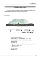
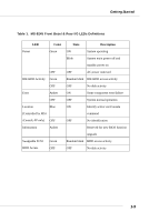
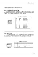
MS-9245 1U Rackmount Server Serial Port Connectors: COM 1 & COM 2 (optional) The mainboard offers two 9-pin DIN connectors as serial ports COM 1 and COM 2. The ports are 16550A high speed communication ports that send/receive 16 bytes FIFOs. You can attach a serial mouse or other serial devices directly to them. 1 2 3 4 5 6 7 8 9 COM 1 COM 1 Pin Definition PIN SIGNAL DESCRIPTION 1 DCD Data Carry Detect 2 SIN Serial In or Receive Data 3 SOUT Serial Out or Transmit Data 4 DTR Data Terminal Ready) 5 GND Ground 6 DSR Data Set Ready 7 RTS Request To Send 8 CTS Clear To Send 9 RI Ring Indicate 9 7 5 3 1 8 6 4 2 COM 2 COM 2 Pin Definition PIN DESCRIPTION PIN DESCRIPTION 1 Data Carrier Detect 2 Receive Data 3 Transmit Data 4 Data Terminal Ready 5 Ground 6 Data Set Ready 7 Request to Send 8 Clear to Send 9 Ring Indicator 10 Ground VGA Connector The mainboard provides a DB 15-pin female connector to connect a VGA monitor. 5 1 15 11 VGA Connector (DB 15-pin) 1-12 Pin Signal Description 1 RED 2 GREEN 3 BLUE 4 N/C 5 GND 6 GND 7 GND 8 GND 9 +5V 10 GND 11 N/C 12 SDA 13 Horizontal Sync 14 Vertical Sync 15 SCL
-
 1
1 -
2
-
3
-
4
-
5
-
6
-
7
-
8
-
9
-
10
-
11
-
12
-
 13
13 -
 14
14 -
 15
15 -
 16
16 -
 17
17 -
 18
18 -
 19
19 -
 20
20 -
 21
21 -
 22
22 -
 23
23 -
24
-
25
-
26
-
27
-
28
-
29
-
30
-
31
-
32
-
33
-
34
-
35
-
36
-
37
-
38
-
39
-
40
-
41
-
42
-
43
-
44
-
45
-
46
-
47
-
48
-
49
-
50
-
51
-
52
-
53
-
54
-
55
-
56
-
57
-
58
-
59
-
60
-
61
-
62
-
63
-
64
-
65
-
66
-
67
-
68
 |
 |
