MSI K1 User Guide - Page 30
Serial ATA Connectors: JSA_11, JSA_22, Optional, Rear Status LED: J20, Optional Serial ATA cable
 |
View all MSI K1 manuals
Add to My Manuals
Save this manual to your list of manuals |
Page 30 highlights
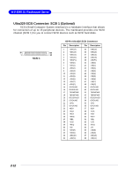
Hardware Setup Rear Status LED: J20 The LED shows the error and power status. Error LED (Amber) Power LED (Green) Serial ATA Connectors: JSA_11, JSA_22 (Optional) The mainboard provides optional Serial ATA connectors supported by Silicon Image Sil3512 single-chip PCI to 2-port Serial ATA host controller. JSA_11 7 1 7 Pin Definition PIN SIGNAL 1 GND 3 TXN 5 RXN 7 GND PIN SIGNAL 2 TXP 4 GND 6 RXP 1 JSA_22 Take out the dust cover and connect to the hard disk devices Optional Serial ATA cable Connect to JSA_11/JSA_22 MSI Reminds You... Please do not fold the Serial ATA cable into 90-degree angle. Otherwise, the loss of data may occur during transmission. 2-11
-
 1
1 -
2
-
3
-
4
-
5
-
6
-
7
-
8
-
9
-
10
-
11
-
12
-
13
-
14
-
15
-
16
-
17
-
18
-
19
-
20
-
21
-
22
-
23
-
24
-
 25
25 -
 26
26 -
 27
27 -
 28
28 -
 29
29 -
 30
30 -
 31
31 -
 32
32 -
 33
33 -
 34
34 -
 35
35 -
36
-
37
-
38
-
39
-
40
-
41
-
42
-
43
-
44
-
45
-
46
-
47
-
48
-
49
-
50
-
51
-
52
-
53
-
54
-
55
-
56
-
57
-
58
-
59
-
60
-
61
-
62
-
63
-
64
-
65
-
66
-
67
-
68
 |
 |

2-11
Hardware Setup
PIN
SIGNAL
PIN
SIGNAL
1
GND
2
TXP
3
TXN
4
GND
5
RXN
6
RXP
7
GND
Pin Definition
Serial ATA Connectors: JSA_11, JSA_22
(Optional)
The mainboard provides optional Serial ATA connectors supported by Silicon
Image Sil3512 single-chip PCI to 2-port Serial ATA host controller.
Connect to JSA_11/JSA_22
Take out the dust cover and
connect to the hard disk
devices
Optional Serial ATA cable
MSI Reminds You...
Please do not fold the Serial ATA cable into 90-degree angle. Otherwise,
the loss of data may occur during transmission.
Rear Status LED: J20
The LED shows the error and power status.
Error LED (Amber)
Power LED (Green)
JSA_22
JSA_11
7
1
7
1