MSI K9A PLATINUM User Guide - Page 11
Installation Guide, How to use this Installation Guide? - mainboard
 |
UPC - 816909034073
View all MSI K9A PLATINUM manuals
Add to My Manuals
Save this manual to your list of manuals |
Page 11 highlights
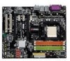
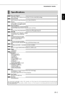
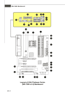
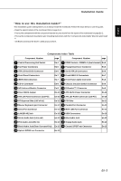
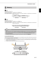
English Installation Guide "How to use this Installation Guide?" This installation guide is designed for you to easily install the mainboard. Follow the steps below to use this guide: - Read the specifications of the mainboard first on page En-1. - Find out the component with the component number at your desire from the layout of the mainboard on page En-2. - Find out the component description and installing instructions with the "Components Index Table" direction and install it. - Set BIOS and install the driver / utiltity at your desire. Components Index Table Component Number page Component Number page 1 Central Processing Unit Socket En-4 3 DDRII Sockets : DIMM1~4 (dual channel) En-5 4 Fan Power Connectors 6 ATA 133 Hard Disk Connector 8 Front Panel Connectors En-6 En-6 En-7 5 Floppy Disk Driver Connector 7 Serial ATA 2.0 Connectors 9 Front USB 2.0 Connectors En-6 En-6 En-7 10 IEEE 1394 Connectors 14 CD-In Connector En-7 En-8 12 Front Panel Audio Connector 15 Chassis Intrusion Switch Connector En-8 En-8 16 IrDA Infrared Module Connector En-8 19 D-BracketTM 2 Connector En-9 20 Clear CMOS Jumper En-10 21 ATX 24-Pin Power Connector En-10 23 ATX 12V Power Connector (2x2-Pin) En-10 25 ATX 12V Power Connector (1x4-Pin) En-10 26 PCI Express Slots (x16/ x4/ x1) En-11 27 PCI Slots En-11 29 Mouse/ Keyboard port Connector En-12 30 Parallel Port Connector En-12 31 Serial Port Connector En-12 34 IEEE 1394 Port Connector En-12 35 LAN (RJ-45) Jack 37 Green Audio Jack (Line-out) En-13 36 USB Connectors En-13 38 Blue Audio Jack En-13 En-13 39 Pink Audio Jack (Mic-In) En-13 40 Orange Audio Jack En-13 41 Black Audio Jack (Rear Surround-Out) En-13 43 Coaxial S/PDIF-out Connector En-13 44 Optical S/PDIF-out Connector En-13 En-3
-
 1
1 -
2
-
3
-
4
-
5
-
 6
6 -
 7
7 -
 8
8 -
 9
9 -
 10
10 -
 11
11 -
 12
12 -
 13
13 -
 14
14 -
 15
15 -
 16
16 -
17
-
18
-
19
-
20
-
21
-
22
-
23
-
24
-
25
-
26
-
27
-
28
-
29
-
30
-
31
-
32
-
33
-
34
-
35
-
36
-
37
-
38
-
39
-
40
-
41
-
42
-
43
-
44
-
45
-
46
-
47
-
48
-
49
-
50
-
51
-
52
-
53
-
54
-
55
-
56
 |
 |
