MSI K9A PLATINUM User Guide - Page 17
D-Bracket, Connector, Description, Green, LEDs signal - overclocking
 |
UPC - 816909034073
View all MSI K9A PLATINUM manuals
Add to My Manuals
Save this manual to your list of manuals |
Page 17 highlights
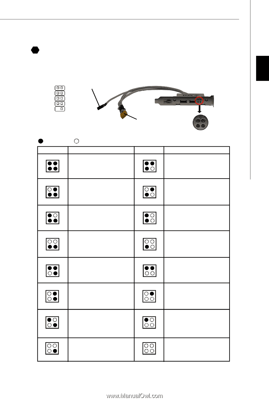
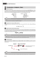
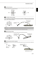
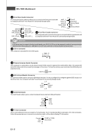
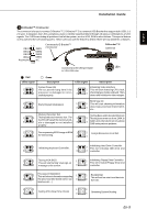
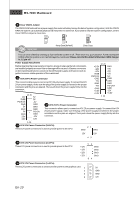
English Installation Guide 19 D-Bracket™ 2 Connector The connector is for you to connect D-Bracket™ 2. D-Bracket™ 2 is a external USB Bracket that support both USB1.1 & 2.0 spec. It integrates four LEDs and allows users to identify system problem through 16 various combinations of LED signals. The 4 LEDs can debug all problems that fail the system, such as VGA, RAM or other failures. This special feature is very useful for the overclocking users. These users can use the feature to detect if there are any problems or failures. 1 2 DBG1 DBR1 DBG2 DBR2 DBG3 DBR3 DBG4 DBR4 Key(no pin) NC 9 10 Connected to D-Bracket™ 2 Connector Connected to the USB pinheader in YELLOW color D-Bracket™ 2 (Optional) 1 2 LEDs 3 4 Red LEDs signal 1 2 3 4 Green Description LEDs signal Description System Power ON The D-LED will hang here if the 1 processor is damaged or not in- 3 stalled properly. Initializing Video Interface 2 This will start detecting CPU clock, 4 checking type ofvideo onboard. Then, detect and initializethe video adapter. 1 2 EarlyChipset Initialization 3 4 BIOS Sign On 1 2 This will start showing information 3 4 about logo, processor brand name, etc... Memory Detection Test Testing Base and Extended Memory 1 2 Testing onboard memory size. The 1 2 Testing base memory from 240K to 3 D-LED will hang if the memory mod4 ule is damaged or not installed 3 4 640K and extended memory above 1MB using various patterns. properly. 1 2 Decompressing BIOS image to RAM 1 2 Assign Resources to all ISA. 3 4 for fast booting. 3 4 1 2 Initializing Keyboard Controller. 1 2 Initializing Hard Drive Controller This will initialize IDE drive and 3 4 3 4 controller. 1 2 Testing VGA BIOS 1 2 Initializing Floppy Drive Controller This will start writing VGA sign-on This will initialize Floppy Drive and 3 4 message to the screen. 3 4 controller. 1 Processor Initialization 2 This will show information regarding 1 2 BootAttempt This will set low stack and boot via 3 4 the processor (like brand name, sys- 3 4 INT 19h. tem bus, etc...) 1 2 1 2 3 Testing RTC (Real Time Clock) 4 3 4 Operating System Booting En-9
-
 1
1 -
2
-
3
-
4
-
5
-
6
-
7
-
8
-
9
-
10
-
11
-
 12
12 -
 13
13 -
 14
14 -
 15
15 -
 16
16 -
 17
17 -
 18
18 -
 19
19 -
 20
20 -
 21
21 -
 22
22 -
23
-
24
-
25
-
26
-
27
-
28
-
29
-
30
-
31
-
32
-
33
-
34
-
35
-
36
-
37
-
38
-
39
-
40
-
41
-
42
-
43
-
44
-
45
-
46
-
47
-
48
-
49
-
50
-
51
-
52
-
53
-
54
-
55
-
56
 |
 |