MSI K9A PLATINUM User Guide - Page 15
Installation Guide - audio
 |
UPC - 816909034073
View all MSI K9A PLATINUM manuals
Add to My Manuals
Save this manual to your list of manuals |
Page 15 highlights
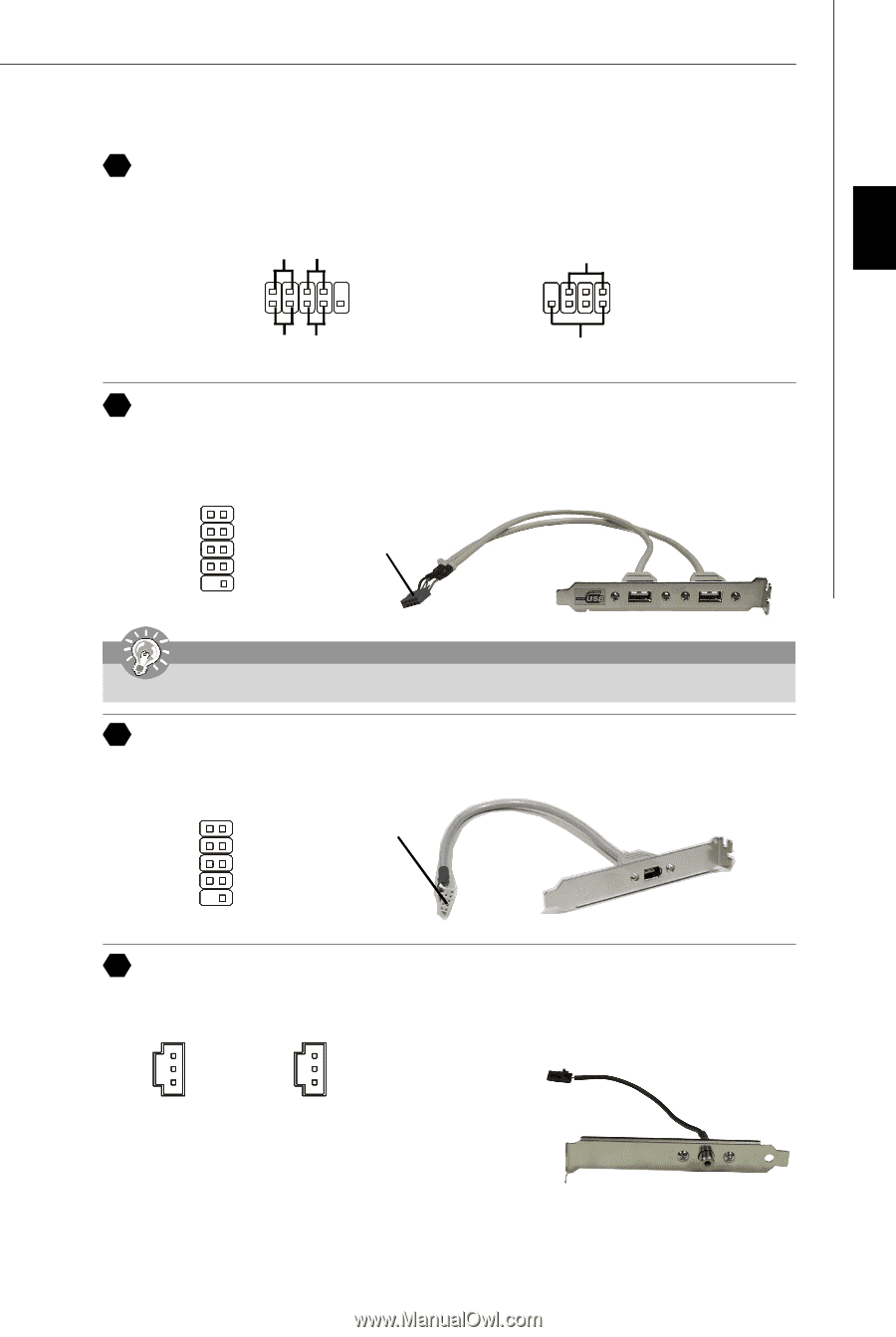
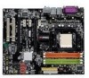
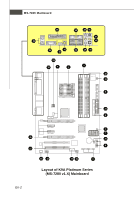
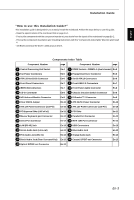
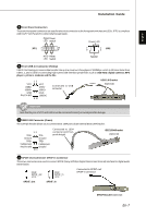
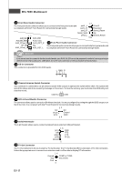
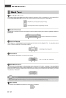
English Installation Guide 8 Front Panel Connectors These two front panel connectors are used for electrical connection to the front panel switches and LEDs. JFP1 is compliant with Intel® Front Panel I/O Connectivity Design Guide. Power Power LED Switch Power LED JFP1 2 1 10 9 7 8 1 JFP2 2 HDD Reset LED Switch Speaker 9 Front USB 2.0 Connector (Yellow) USB 2.0 technology increases data transfer rate up to a maximum throughput of 480Mbps, which is 40 times faster than USB 1.1, and is ideal for connecting high-speed USB interface peripherals such as USB HDD, digital cameras, MP3 players, printers, modems and the like. 1 2 VCC VCC USB0- USB1- USB0+ USB1+ GND Key (no pin) GND USBOC 9 10 Connected to USB connector USB 2.0 Bracket (Optional) Important Note that the pins of VCC and GND must be connected correctly to avoid possible damage. 10 IEEE 1394 Connector (Green) The 1394 pin header allows you to connect IEEE 1394 ports via an external IEEE1394 bracket. 1 2 TPA+ TPA- Ground Ground TPB+ TPB- Cablepower Cablepower Key (no pin) Ground 9 10 Connected to 1394 connector (with foolproof design) IEEE1394 Bracket (Optional) 11 SPDIF-Out Connector/ SPDIF-In Connector These two connectors are used to connect SPDIF (Sony & Philips Digital Interconnect Format) interface for digital audio transmission. GND SPDIF_out VCC GND SPDIF_in VCC Connected to SPDIF-out/ SPDIF-in connector SPDIF_Out SPDIF_In SPDIF Bracket (Optional) En-7
-
 1
1 -
2
-
3
-
4
-
5
-
6
-
7
-
8
-
9
-
 10
10 -
 11
11 -
 12
12 -
 13
13 -
 14
14 -
 15
15 -
 16
16 -
 17
17 -
 18
18 -
 19
19 -
 20
20 -
21
-
22
-
23
-
24
-
25
-
26
-
27
-
28
-
29
-
30
-
31
-
32
-
33
-
34
-
35
-
36
-
37
-
38
-
39
-
40
-
41
-
42
-
43
-
44
-
45
-
46
-
47
-
48
-
49
-
50
-
51
-
52
-
53
-
54
-
55
-
56
 |
 |