MSI K9A PLATINUM User Guide - Page 18
En-10 - ram
 |
UPC - 816909034073
View all MSI K9A PLATINUM manuals
Add to My Manuals
Save this manual to your list of manuals |
Page 18 highlights
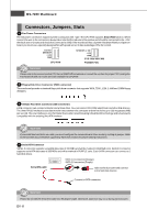
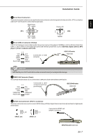
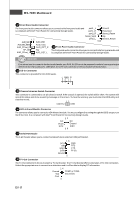
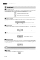
MS-7280 Mainboard 20 Clear CMOS Jumper The CMOS RAM onboard has a power supply from external batteryto keep thedata of system configuration. With the CMOS RAM, the system can automaticallyboot OS every time it is turned on. If you want to clear the system configuration, set the Clear CMOS Jumper to clear data. 1 1 1 Important 3 Keep Data (default) 3 Clear Data You can clear CMOS by shorting 2-3 pin while the system is off. Then return to 1-2 pin position. Avoid clearing the CMOS while the system is on; it will damage the mainboard. Please note that the default of the Clear CMOS Jumper is 1-2 pin off. Power Supply Attachment 12 24 Before inserting the power supplyconnector, always make sure that all components are installed properly to ensure that no damage will be caused. All power connectors on the mainbnoard have to connect to the ATX power supply and have to work together to ensure stable operation of the mainboard. +3.3V +12V +12V 5VSB GND +5V +5V +5V 21 ATX 24-Pin Power Connector PWR OK GND NC GND This connector allowsyou to connect anATX 24-pin power supply. To connect theATX 24-pin power supply, make sure the plug of the power supply is inserted in the proper orientation and the pins are aligned. Then push down the power supply firmly into the connector. +5V GND +5V GND +3.3V GND GND PS-ON# GND -12V 10 20 12V 5V +3.3V +3.3V 1 13 5VSB 5V PWR OK -5V GND 5V GND 5V GND 3.3V GND GND GND PS-ON GND -12V 22 ATX 20-Pin Power Connector This connector allows you to connect an ATX 20-pin power supply. To connect the ATX 20-pin power supply, make sure the plug of the power supply is inserted in the proper orientation and the pins are aligned. Then push down the power supply firmly into the connector. 3.3V 3.3V 1 11 23 ATX 12V Power Connector (2x2-Pin) These 12V power connectors is used to provide power to the CPU. 21 GND GND 12V 12V 43 24 ATX 12V Power Connector (2x4-Pin) These 12V power connectors is used to provide power to the CPU. +12V +12V +12V +12V 51 GND GND GND GND 84 25 ATX 12V Power Connector (1x4-Pin) These 12V power connectors is used to provide power to the graphics card. 1 2 3 4 5V GND GND 12V En-10
-
 1
1 -
2
-
3
-
4
-
5
-
6
-
7
-
8
-
9
-
10
-
11
-
12
-
 13
13 -
 14
14 -
 15
15 -
 16
16 -
 17
17 -
 18
18 -
 19
19 -
 20
20 -
 21
21 -
 22
22 -
 23
23 -
24
-
25
-
26
-
27
-
28
-
29
-
30
-
31
-
32
-
33
-
34
-
35
-
36
-
37
-
38
-
39
-
40
-
41
-
42
-
43
-
44
-
45
-
46
-
47
-
48
-
49
-
50
-
51
-
52
-
53
-
54
-
55
-
56
 |
 |
