MSI Keeper User Guide
MSI Keeper Manual
 |
View all MSI Keeper manuals
Add to My Manuals
Save this manual to your list of manuals |
MSI Keeper manual content summary:
- MSI Keeper | User Guide - Page 1
MS-9641 (V2.X) Mainboard G52-96411x1 i - MSI Keeper | User Guide - Page 2
obtained from the user's manual, please contact your place of purchase or local distributor. Alternatively, please try the following help resources for further guidance. Visit the MSI website at http://global.msi.com.tw/index.php? func=service for FAQ, technical guide, BIOS updates, driver updates - MSI Keeper | User Guide - Page 3
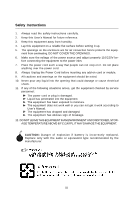
1. Always read the safety instructions carefully. 2. Keep this User's Manual for future reference. 3. Keep this equipment . 11. If any of the following situations arises, get the equipment checked by service personnel: The power cord or plug is damaged. Liquid has penetrated into the equipment. - MSI Keeper | User Guide - Page 4
, if not installed and used in accordance with the instructions, may cause harmful interference to radio communications. However, with the emission limits. VOIR LANOTICE D'INSTALLATIONAVANT DE RACCORDER AU RESEAU. Micro-Star International MS-9641 This device complies with Part 15 of the FCC Rules. - MSI Keeper | User Guide - Page 5
WEEE (Waste Electrical and Electronic Equipment) Statement v - MSI Keeper | User Guide - Page 6
vi - MSI Keeper | User Guide - Page 7
vii - MSI Keeper | User Guide - Page 8
Support ...iii Safety Instructions ...iii FCC-B Radio Frequency Interference Statement v W EEE (Waste Electrical and Electronic Equipment) Statement v Chapter 1 Getting Started 1-1 Mainboard Specifications 1-2 Mainboard Layout 1-4 Chapter 2 Hardware Setup 2-1 Quick Components Guide - MSI Keeper | User Guide - Page 9
Getting Started Chapter 1 Getting Started Thank you for choosing the MS-9641 v2.x Micro-ATX mainboard. The mainboard is based on Intel® 945GME and ICH7/ICH7R chipset for optimal system efficiency. Designed to fit the advanced Intel® Core Duo/Core Solo Series processor, the mainboard delivers a high - MSI Keeper | User Guide - Page 10
Mainboard Specifications Processor - Intel® Core Duo/Core Solo Series processors in the 478 Micro FC-PGA package. - Supports 3 pin CPU Fan Pin-Header with Fan Speed Control. - Supports Intel Core Duo Technology. FSB - 533/ 667 MHz Chipset - North Bridge: Intel® 945GME chipset - South Bridge: Intel - MSI Keeper | User Guide - Page 11
Getting Started Watch Dog Timer - 255 level Form Factor - Micro-ATX (24.3cm X 22.7 cm) Mounting - 8 mounting holes Accessory - CPU Retention Module (optional) - CPU Cooler (optional) 1-3 - MSI Keeper | User Guide - Page 12
MS-9641 Mainboard Mainboard Layout J V GA 0 COM1 COM2 C L R_ C MOS 0 JLCD1 ATX1 BATT + AUXFAN0 J0 Winbond W83627EHG JUSB0 J LA N0 J LA N1 J LA N2 DIMM1 DIMM0 Intel 945GME SYSF AN1 JPW0 SM_BUS CP UFAN0 IDEB0 J _L A N1 C F0 JLPC1 JCFV_SE L J LA N3 JLAN4 JLA N5 J3 PCI0 LAN_LED J P1 - MSI Keeper | User Guide - Page 13
Hardware Setup Chapter 2 Hardware Setup This chapter provides you with the information about hardware setup procedures. While doing the installation, be careful in holding the components and follow the installation procedures. For some components, if you install in the wrong orientation, the - MSI Keeper | User Guide - Page 14
MS-9641 Mainboard Quick Components Guide JLCD1, p.2-16 CLR_CMOS0, p.2-24 COM2, p.2-15 ATX1, p.2-8 AUXFAN0, p.2-13 J0, p.2-16 SYSFAN1, p.2-13 SM_BUS, p.2-15 Front Panel, p.2-9 DIMM0/1, p.2-6 JPW0, p.2-8 CPUFAN0, p.2-13 CPU, p.2-3 J3, p.2-17 JTV0, p.2- - MSI Keeper | User Guide - Page 15
Hardware Setup CPU (Central Processing Unit) The mainboard supports Intel® Core Duo/Core Solo processor in the 478 pin package. The mainboard uses a CPU socket called mPGA478 for easy CPU installation. W hen you are - MSI Keeper | User Guide - Page 16
MS-9641 Mainboard CPU & Cooler Set Installation 1. Loose the screw on the CPU socket with a tank screwdriver in clockwise direction. 2. Place the CPU on top of the socket. Make sure to align the gold arrow on the CPU with the arrow key on the socket. 4. On the front end of the CPU socket is a - MSI Keeper | User Guide - Page 17
Hardware Setup 5. Mount the cooler set (fan & heatsink bundled) on top of the CPU and fit it into the retention mechanism. 6. Secure the levers to lock the cooler set. 7. Connect the fan power cable from the mounted fan to the 3-pin fan power connector on the board. 2-5 - MSI Keeper | User Guide - Page 18
1.8V 64x2=128 pin 56x2=112 pin Memory Population Rules Slot Memory Module DIMM 0 (Bank 0 & 1) S/D DIMM 1 (Bank 2 & 3) S/D Maximum System Memory Supported Total Memory 128MB~2GB 128MB~2GB 128MB~4GB S: Single Side D: Double Side Important - Make sure that you install memory modules of - MSI Keeper | User Guide - Page 19
close if the DIMM is properly seated. Important You can barely see the golden finger if the DIMM is properly inserted in the DIMM slot. 3. Manually check if the DIMM has been locked in place by the retaining clips at the sides. 4. Follow the same procedures to install more DIMMs if - MSI Keeper | User Guide - Page 20
MS-9641 Mainboard Power Supply ATX 24-Pin Power Connector: ATX1 This connector allows you to connect an ATX 24-pin power supply. To connect the ATX 24-pin power supply, make sure the plug of the power supply is inserted in the proper orientation and the pins are aligned. Then push down the power - MSI Keeper | User Guide - Page 21
Front Panel WAN LAN LAN Bypass Disable WAN LAN or WAN LAN Bypass Enable LAN WAN LAN Hardware Setup Serial Port Connector The serial port is a 16550A high speed communications port that sends/ receives 16 bytes FIFOs. You can attach a serial mouse or other serial devices directly to the connector. - MSI Keeper | User Guide - Page 22
MS-9641 Mainboard LAN (RJ-45) Jack The standard RJ-45 jack is for connection to single Local Area Network (LAN). You can connect a network cable to it. Activity Indicator Link Indicator LED Color Left Orange Green Right Orange LED State Off On (steady state) On (blinking) Off On On Condition - MSI Keeper | User Guide - Page 23
The mainboard provides a one-channel Ultra ATA 100 bus Master IDE controller that supports PIO mode 0~4, Bus Master, and Ultra DMA 66/100 function. You can supplied by hard disk vendors for jumper setting instructions. Compact Flash Card Slot: CF0 This is the slot for Type II Compact Flash ( - MSI Keeper | User Guide - Page 24
MS-9641 Mainboard Serial ATAII Connectors: SATA1~SATA4 SATA1~SATA4 are high-speed Serial ATA interface ports. Each supports serial ATA data rates of 3G b/s . Both connectors are fully compliant with Serial ATA 2.0 specifications. Each Serial ATA connector can connect to 1 hard disk device. - MSI Keeper | User Guide - Page 25
Connectors: CPUFAN0, SYSFAN1, AUXFAN0 The fan power connectors support system cooling fan with +12V. W hen connecting the front panel switches and LEDs. The JFP1 is compliant with Intel® Front Panel I/O Connectivity Design Guide. Reset HDD Switch LED + - - + JFP1 9 1 10 2 + - Power Power - MSI Keeper | User Guide - Page 26
USB Connector: F_USB2 The mainboard provides one USB 2.0 pinheader (optional USB 2.0 bracket available) that are compliant with Intel® I/O Connectivity Design Guide. USB 2.0 technology increases data transfer rate up to a maximum throughput of 480Mbps, which is 40 times faster than USB 1.1, and is - MSI Keeper | User Guide - Page 27
Hardware Setup SMBus Connector: SM_BUS The mainboard provides one I2C (also known as I2C) Bus connector for users to connect System Management Bus (SMBus) interface. SM_BUS 6 1 Pin Definition PIN SIGNAL 1 GND 2 VCC5V 3 SMBus_Clock 4 SMBus_Data 5 +12V 6 Power Button TV-Out Connector: - MSI Keeper | User Guide - Page 28
MS-9641 Mainboard LCD Module Connector: JLCD1 This connector is used to connect TTL UART LCD Module. JLCD1 1 Pin Definition PIN SIGNAL 1 +5V 2 SINB 3 GND 4 SOUTB Keyboard/Mouse Connector: J0 This connector is used to connect a mouse/keyboard. J0 9 1 10 2 Pin Definition PIN - MSI Keeper | User Guide - Page 29
Hardware Setup LAN_LED LAN_LED 2 26 1 25 Pin Definition Pin Description 1 LAN2_LED_ACT 3 LAN2_LED_LINK10/100 5 LAN1_LED_ACT 7 LAN1_LED_LINK10/100 9 LAN4_LED_ACT 11 LAN4_LED_LINK10/100 13 LAN3_LED_ACT 15 LAN3_LED_LINK10/100 17 LAN5_LED_ACT 19 LAN5_LED_LINK10/100 21 LAN6_LED_ACT 23 - MSI Keeper | User Guide - Page 30
MS-9641 Mainboard LAN Bypass Definition Bypass setting in BIOS Power status BIOS Bypass Se ing On Bypass mode a er powe r on Bypass mode a er powe r off Off (All segment or by each segment are controllable) Disable Enable Disable Enable Bypass Behavior A B A B Pass Through Behavior: A Bypass - MSI Keeper | User Guide - Page 31
Hardware Setup LAN5, LAN6 have no by pass function. Programming Guide LPC I/O address : 5E SMBus address: 0X00 (optional) 1. Power ON State Bypass Control Status Register Set/Read bypass mode Default Value: 0x00 (Base on Customer Demand) - MSI Keeper | User Guide - Page 32
MS-9641 Mainboard Signal Action Segment Segment 1 Segment 2 Segment 3 Segment 4 Signal Name RELAY_SET1# RESET_RESET1# BYPASS1_LED# RELAY_SET2# RESET_RESET2# BYPASS2_LED# RELAY_SET3# RESET_RESET3# BYPASS3_LED# RELAY_SET4# RESET_RESET4# BYPASS4_LED# D esc ription Enable LAN1 bypass Enable LAN1 - MSI Keeper | User Guide - Page 33
Hardware Setup 3. Power Off to Bypass Control Register Enable/Disable Low Voltage Detect (3.08VDETECT) input for bypass mode W hen 3.08VDETECT pin input 0, then low voltage detected. This register sets power off behavior for Segment 1~5 3.08VDETECT - Input from Voltage Supervisor. W hen +12V input - MSI Keeper | User Guide - Page 34
MS-9641 Mainboard Method 1: GPIO control Bypass (GPIO Mode) ByPass Normal SB GPIO38(Relay1) High Low SB GPIO39(Relay2) High Low Note: GPIO Mode has two configuration. One is GPIO38,39 controlling together; the other is GPIO38,39 controlling individually. Method 2: LPC Control Bypass (LPC - MSI Keeper | User Guide - Page 35
Sample Code (M ethod 2: LPC Mode) Hardware Setup Control LPC LAN mov al,0fh mov dx,005eh out dx,al ;Select LPC Mode (bit 4 =1) Note: bit 0 = 1, change LAN 1, 2 to bypass, bit 0 = 0, change LAN 1, 2 to normal (power on status) bit 1 = 1, change LAN 3, 4 to bypass, bit 1 = 0, change LAN 3, 4 to - MSI Keeper | User Guide - Page 36
MS-9641 Mainboard Jumpers Clear CMOS Jumper: CLR_CMOS0 There is a CMOS RAM onboard that has a power supply from external battery to keep the data of system configuration. With the CMOS RAM, the system can automatically boot OS every time it is turned on. If you want to clear the system configuration - MSI Keeper | User Guide - Page 37
Hardware Setup GMCH Voltage Jumper: J2 This jumper is used to adjust the voltage of the Intel 945GME GMCH (Graphics and Memory Controller Hub) as a way to enhance graphics performance. 1 J2 3 13 1 1.05V 1.5V AT/ATX Power Select Jumper: J5 1 J5 1 3 AT 1 3 ATX JCF_SEL & JCFV_SEL 1 JCF_SEL - MSI Keeper | User Guide - Page 38
MS-9641 Mainboard Slot Golden Finger TOP View B94 B1 BOTTOM View A94 A1 PCI (Peripheral Component Interconnect) Slot The PCI slots support LAN cards, SCSI cards, USB cards, and other add-on cards that comply with PCI specifications. At 32 bits and 33 MHz, it yields a throughput - MSI Keeper | User Guide - Page 39
Chapter 3 BIOS Setup BIOS Setup This chapter provides information on the BIOS Setup program and allows you to configure the system for optimum use. You may need to run the Setup program when: ² An error message appears on the screen during the system booting up, and requests you to run SETUP. ² - MSI Keeper | User Guide - Page 40
MS-9641 Mainboard Entering Setup Power on the computer and the system will start POST (Power On Self Test) process. W hen the message below appears on the screen, press key to enter Setup. Press F1 to enter SETUP If the message disappears before you respond and you still wish to enter Setup, - MSI Keeper | User Guide - Page 41
BIOS Setup Control Keys Enter> Move to the previous item Move to the next item Move to the item in the left hand Move to the item in the right hand Select the item Jumps to the Exit menu or returns to the main menu from a submenu Increase the numeric value or - MSI Keeper | User Guide - Page 42
available on your system's chipset. Boot Use this menu to specify the priority of boot devices. Security Use this menu to set Supervisor and User Passwords. System This entry shows your system summary. PC Health This entry monitors your hardware health status. Exit This menu allows you to load the - MSI Keeper | User Guide - Page 43
:ss) The time format is . IDE Channel 0 Master/Slave, IDE Channel 1 Master/Slave IDE Channel 0 Master Press PgUp/ or PgDn/ to select [Manual], [None] or [Auto] type. Note that the specifications 3-5 - MSI Keeper | User Guide - Page 44
disk drive type is not matched or listed, you can use [Manual] to define your own drive type manually. The settings are [CHS], [LBA], [Large], [Auto]. . The BIOS usually detects the correct video type automatically. The BIOS supports a secondary video subsystem, but you do not select it in Setup - MSI Keeper | User Guide - Page 45
Advanced BIOS Setup Advanced BIOS Features Virus Warning The item is to set the Virus W arning feature for IDE Hard Disk boot sector protection. If the function is enabled and any attempt to write data into this area is made, BIOS will display a warning message on screen and beep. CPU L3 Cache - MSI Keeper | User Guide - Page 46
you normally disable quick POST. Better to find a problem during POST than lose data during your work. Programmable Interrupt Controller). Due to compliance with PC2001 design guide, the system is able to run in APIC You need to select the MPS version supported by your operating system. To find out - MSI Keeper | User Guide - Page 47
[By SPD] enables DRAM timing to be determined automatically by BIOS based on the configurations on the SPD. Selecting [Manual] allows users to configure the following fields manually. CAS Latency Time This controls the timing delay (in clock cycles) before SDRAM starts a read command after receiving - MSI Keeper | User Guide - Page 48
MS-9641 Mainboard **VGA Setting** The following items allow you to configure the VGA settings of the system. PEG/Onchip VGA Control This setting allows you to select whether to use the onchip graphics processor or the PCI Express card. W hen set to [Onchip VGA], the motherboard boots up using the - MSI Keeper | User Guide - Page 49
block mode (most new drives do), select [Enabled] for automatic detection of the optimal number of block read/writes per sector the drive can support. IDE DM A Transfer Access Setting to [Enabled] will open DMA bus master and execute DMA action in DOS, which will make the data transferring faster - MSI Keeper | User Guide - Page 50
mode for each device. IDE Primary/Secondary Master/Slave UDMA Ultra DMA 33/66/100/133 implementation is possible only if your IDE hard drive supports it and the operating environment includes a DMA driver (W indows ME, XP or a third-party IDE bus master driver). If your hard drive and your system - MSI Keeper | User Guide - Page 51
hard disks) or installed operating systems. USB Controller, USB 2.0 Controller This setting is used to enable/disable the onboard USB / USB2.0 controller. USB Keyboard/Mouse Support Set to [Enabled] if your need to use a USB-interfaced keyboard/mouse in the operating system that does not - MSI Keeper | User Guide - Page 52
MS-9641 Mainboard Super IO Device Onboard Serial Port 1 / 2 Select an address and corresponding interrupt for Serial Port 1/2. UART M ode Select This setting allows you to specify the operation mode for serial port 2. [Normal] RS-232C Serial Port [IrDA] IrDA-compliant Serial Infrared Port [ - MSI Keeper | User Guide - Page 53
, such as W indows 98SE/2000/ME, select [Enabled]. ACPI Suspend Type This item specifies the power saving modes for ACPI function. If your operating system supports ACPI, such as W indows 98SE, W indows ME and W indows 2000, you can choose to enter the Standby mode in S1 (POS) or S3 (STR) fashion - MSI Keeper | User Guide - Page 54
MS-9641 Mainboard cations/files is saved to main memory that remains powered while most other hardware components turn off to save energy. The information stored in memory will be used to restore the system when a "wake up" event occurs. Soft-Off by PWR-BTTN This feature allows users to configure - MSI Keeper | User Guide - Page 55
generated by modulating the pulses so that the spikes of the pulses are reduced to flatter curves. Important 1. If you do not have any EMI problem, leave the setting at [Disabled] for optimal system stability and performance. But if you are plagued by EMI, select the value of Spread Spectrum for - MSI Keeper | User Guide - Page 56
MS-9641 Mainboard Boot Removable Device Priority This setting allows users to set the priority of the removable devices. Refer to the Item Help on the right pane for instructions. 3-18 - MSI Keeper | User Guide - Page 57
hard disk devices. Refer to the Item Help on the right pane for instructions. CD-ROM Boot Priority This setting allows users to set the boot priority specified CD-ROM devices. Refer to the Item Help on the right pane for instructions. First / Second / Third Boot Device The items allow you to set the - MSI Keeper | User Guide - Page 58
at boot. Security Option This specifies the type of BIOS password protection that is implemented. Settings are described below: Option [Setup] [System] Description The password prompt appears only when end users try to run Setup. A password prompt appears every time when the computer is powered on - MSI Keeper | User Guide - Page 59
System BIOS Setup System Summary These items show the hardware specifications of your system. Read only. Halt On The setting determines whether the system will stop if an error is detected at boot. W hen the system stops for the errors preset, it will halt on for 15 seconds and then automatically - MSI Keeper | User Guide - Page 60
MS-9641 Mainboard PC Health Smart Fan Setting The sub-menu is used to control fan speeds for optimal system performance. Smart SYSFan1 / CPUFan1 / SYSFan2 Temperature Select a temperature setting here, and if the temperature of the CPU/system climbs up to the selected temperature setting, the system - MSI Keeper | User Guide - Page 61
BIOS Setup SYSFan1 / CPUFan1 / SYSFan2 Tolerance Value You can select a fan tolerance value here for the specific range for the Smart SYSFan1 / CPUFan1 / SYSFan2 Temperature items. If the current temperatures of the fans reach to the maximum threshold (the temperatures set in the Smart SYSFan1 / - MSI Keeper | User Guide - Page 62
MS-9641 Mainboard Exit Load Fail-Safe Defaults Use this menu to load the default values set by the BIOS vendor for stable system performance. Load Optimized Defaults Use this menu to load the default values set by the mainboard manufacturer specifically for optimal performance of the mainboard. Save
-
 1
1 -
 2
2 -
 3
3 -
 4
4 -
 5
5 -
 6
6 -
 7
7 -
8
-
9
-
10
-
11
-
12
-
13
-
14
-
15
-
16
-
17
-
18
-
19
-
20
-
21
-
22
-
23
-
24
-
25
-
26
-
27
-
28
-
29
-
30
-
31
-
32
-
33
-
34
-
35
-
36
-
37
-
38
-
39
-
40
-
41
-
42
-
43
-
44
-
45
-
46
-
47
-
48
-
49
-
50
-
51
-
52
-
53
-
54
-
55
-
56
-
57
-
58
-
59
-
60
-
61
-
62
 |
 |

MS-9641 (V2.X) Mainboard
G52-96411x1