MSI Keeper User Guide - Page 27
SMBus Connector: SM_BUS, Serial Port Connector: COM 2, TV-Out Connector: JTV0
 |
View all MSI Keeper manuals
Add to My Manuals
Save this manual to your list of manuals |
Page 27 highlights
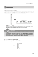
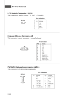
Hardware Setup SMBus Connector: SM_BUS The mainboard provides one I2C (also known as I2C) Bus connector for users to connect System Management Bus (SMBus) interface. SM_BUS 6 1 Pin Definition PIN SIGNAL 1 GND 2 VCC5V 3 SMBus_Clock 4 SMBus_Data 5 +12V 6 Power Button TV-Out Connector: JTV0 The mainboard provides a TV-Out connector. JTV0 2 1 5 Pin Definition Pin Description 1 TVGND 3 LY 5 LC Pin Description 2 LCVBS 4 TVGND 6 Key (no pin ) Serial Port Connector: COM 2 This connector is a 16550A high speed communications port that sends/receives 16 bytes FIFOs. You can attach a serial device to it. 2 10 1 9 COM2 Pin Definition PIN SIGNAL 1 DCD 2 SIN 3 SOUT 4 DTR 5 GND 6 DSR 7 RTS 8 CTS 9 RI DESCRIPTION Data Carry Detect Serial In or Receive Data Serial Out or Transmit Data Data Terminal Ready Ground Data Set Ready Request To Send Clear To Send Ring Indicate 2-15
-
 1
1 -
2
-
3
-
4
-
5
-
6
-
7
-
8
-
9
-
10
-
11
-
12
-
13
-
14
-
15
-
16
-
17
-
18
-
19
-
20
-
21
-
 22
22 -
 23
23 -
 24
24 -
 25
25 -
 26
26 -
 27
27 -
 28
28 -
 29
29 -
 30
30 -
 31
31 -
 32
32 -
33
-
34
-
35
-
36
-
37
-
38
-
39
-
40
-
41
-
42
-
43
-
44
-
45
-
46
-
47
-
48
-
49
-
50
-
51
-
52
-
53
-
54
-
55
-
56
-
57
-
58
-
59
-
60
-
61
-
62
 |
 |
