MSI Keeper User Guide - Page 25
Fan Power Connectors: CPUFAN0, SYSFAN1, AUXFAN0, Front Panel Connectors: JFP1
 |
View all MSI Keeper manuals
Add to My Manuals
Save this manual to your list of manuals |
Page 25 highlights
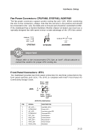
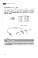
Hardware Setup Fan Power Connectors: CPUFAN0, SYSFAN1, AUXFAN0 The fan power connectors support system cooling fan with +12V. W hen connecting the wire to the connectors, always note that the red wire is the positive and should be connected to the +12V, the black wire is Ground and should be connected to GND. If the mainboard has a System Hardware Monitor chipset on-board, you must use a specially designed fan with speed sensor to take advantage of the CPU fan control. GND +1 2V SE NS OR SE NS OR +1 2V GND CPUFAN0 SYSFAN1 SE NS OR GND +1 2V AUXFAN0 Important Please refer to the recommended CPU fans at Intel® official website or consult the vendors for proper CPU cooling fan. Front Panel Connectors: JFP1 The mainboard provides two front panel connectors for electrical connection to the front panel switches and LEDs. The JFP1 is compliant with Intel® Front Panel I/O Connectivity Design Guide. Reset HDD Switch LED + - - + JFP1 9 1 10 2 + - Power Power/ Switch Suspend LED JFP1 Pin Definition PIN SIGNAL 1 HD_LED + 2 FP PW R/SLP 3 HD_LED - 4 FP PW R/SLP 5 RST_SW - 6 PW R_SW + 7 RST_SW + 8 PW R_SW - 9 RSVD_DNU DESCRIPTION Hard disk LED + Power LED + Hard disk active LED Suspend LED + Reset Switch PowerSwitch + Reset Switch + PowerSwitch Reserved. 2-13
-
 1
1 -
2
-
3
-
4
-
5
-
6
-
7
-
8
-
9
-
10
-
11
-
12
-
13
-
14
-
15
-
16
-
17
-
18
-
19
-
 20
20 -
 21
21 -
 22
22 -
 23
23 -
 24
24 -
 25
25 -
 26
26 -
 27
27 -
 28
28 -
 29
29 -
 30
30 -
31
-
32
-
33
-
34
-
35
-
36
-
37
-
38
-
39
-
40
-
41
-
42
-
43
-
44
-
45
-
46
-
47
-
48
-
49
-
50
-
51
-
52
-
53
-
54
-
55
-
56
-
57
-
58
-
59
-
60
-
61
-
62
 |
 |
