MSI Keeper User Guide - Page 31
Hardware Setup, Programming Guide, Bit Definition
 |
View all MSI Keeper manuals
Add to My Manuals
Save this manual to your list of manuals |
Page 31 highlights
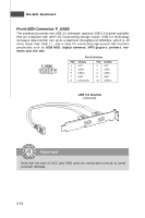
Hardware Setup LAN5, LAN6 have no by pass function. Programming Guide LPC I/O address : 5E SMBus address: 0X00 (optional) 1. Power ON State Bypass Control Status Register Set/Read bypass mode Default Value: 0x00 (Base on Customer Demand) Bit Definition Bit Field 03:00 4 5 6 7 Power ON State Bypass Control Status Register Name Value Segment 1 to 4 Segment control bit. Each bit corresponds to a specific segment numbered 1 thru 4. Write: 1: Force Bypass 0: Force Pass Through Read: 1: Bypass Mode 0: Pass Through Mode Path sel 0:LPC Control LAN 1:GPIO Control LAN reserved reserved GPIO sel 0:GPIO38 and GPIO39 :control LAN1,LAN2 1:GPIO38 controls LAN1,GPIO39 controls LAN2 2-19
-
 1
1 -
2
-
3
-
4
-
5
-
6
-
7
-
8
-
9
-
10
-
11
-
12
-
13
-
14
-
15
-
16
-
17
-
18
-
19
-
20
-
21
-
22
-
23
-
24
-
25
-
 26
26 -
 27
27 -
 28
28 -
 29
29 -
 30
30 -
 31
31 -
 32
32 -
 33
33 -
 34
34 -
 35
35 -
 36
36 -
37
-
38
-
39
-
40
-
41
-
42
-
43
-
44
-
45
-
46
-
47
-
48
-
49
-
50
-
51
-
52
-
53
-
54
-
55
-
56
-
57
-
58
-
59
-
60
-
61
-
62
 |
 |

2-19
Hardware Setup
LAN5, LAN6 have no by pass function.
Programming Guide
LPC I/O address : 5E
SMBus address: 0X00 (optional)
1.
Power ON State Bypass Control Status Register
Set/Read bypass mode
Default Value: 0x00 (Base on Customer Demand)
Bit Definition
Bit Field
Name
Value
Segment control bit. Each bit corresponds to a specific segment
numbered 1 thru 4.
Write
:
1: Force Bypass
0: Force Pass Through
Read
:
1: Bypass Mode
0: Pass Through Mode
0
:
LPC Control LAN
1
:
GPIO Control LAN
5
reserved
6
reserved
0
:
GPIO38 and GPIO39
:
control LAN1,LAN2
1
:
GPIO38 controls LAN1
,
GPIO39 controls LAN2
Power ON State Bypass Control Status Register
7
GPIO sel
03:00
Segment
1 to 4
4
Path sel