MSI MEG X570S ACE MAX User Manual - Page 20
Back Panel, Connectors, Internal Connectors, Buttons, 1x USB 3.2 Gen 2x2 20Gbps Type-C port
 |
View all MSI MEG X570S ACE MAX manuals
Add to My Manuals
Save this manual to your list of manuals |
Page 20 highlights
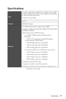
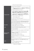
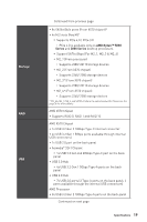
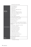
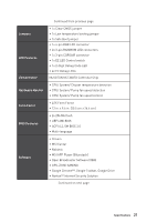
Continued from previous page Back Panel Connectors ∙∙1x Clear CMOS Button ∙∙1x Flash BIOS Button ∙∙4x USB 2.0 ports ∙∙4x USB 3.2 Gen 1 5Gbps Type-A ports ∙∙1x LAN(RJ45) port ∙∙3x USB 3.2 Gen 2 10Gbps Type-A ports ∙∙1x USB 3.2 Gen 2x2 20Gbps Type-C port ∙∙2x Wi-Fi Antenna connectors ∙∙5x OFC audio jacks ∙∙1x Optical S/PDIF Out connector Internal Connectors Buttons ∙∙1x 24-pin ATX main power connector ∙∙2x 8-pin ATX 12V power connectors ∙∙8x SATA 6Gb/s connectors ∙∙4x M.2 slots (M-Key) ∙∙2x USB 2.0 connectors (support additional 4 USB ports) ∙∙2x USB 3.2 Gen 1 5Gbps connectors (support additional 4 USB ports) ∙∙1x USB 3.2 Gen 2 10Gbps Type-C connector ∙∙1x 4-pin CPU fan connector ∙∙1x 4-pin water-pump connector ∙∙6x 4-pin system fan connectors ∙∙1x Front panel audio connector ∙∙2x System panel connectors ∙∙1x TPM module connector ∙∙1x Chassis Intrusion connector ∙∙2x 2-pin Thermal sensors connectors ∙∙1x Water Flow Meter connector ∙∙1x Tuning Controller connector ∙∙1x Power button ∙∙1x Reset button Continued on next page 20 Specifications
-
 1
1 -
2
-
3
-
4
-
5
-
6
-
7
-
8
-
9
-
10
-
11
-
12
-
13
-
14
-
 15
15 -
 16
16 -
 17
17 -
 18
18 -
 19
19 -
 20
20 -
 21
21 -
 22
22 -
 23
23 -
 24
24 -
 25
25 -
26
-
27
-
28
-
29
-
30
-
31
-
32
-
33
-
34
-
35
-
36
-
37
-
38
-
39
-
40
-
41
-
42
-
43
-
44
-
45
-
46
-
47
-
48
-
49
-
50
-
51
-
52
-
53
-
54
-
55
-
56
-
57
-
58
-
59
-
60
-
61
-
62
-
63
-
64
-
65
-
66
-
67
-
68
-
69
-
70
-
71
-
72
-
73
-
74
 |
 |