MSI MEG X570S ACE MAX User Manual - Page 41
Using the supplied HDD LED cable to connect the JMB connector and JFP1's HDD, pins pin 1 & pin3.
 |
View all MSI MEG X570S ACE MAX manuals
Add to My Manuals
Save this manual to your list of manuals |
Page 41 highlights
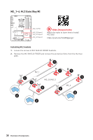
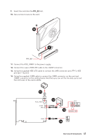
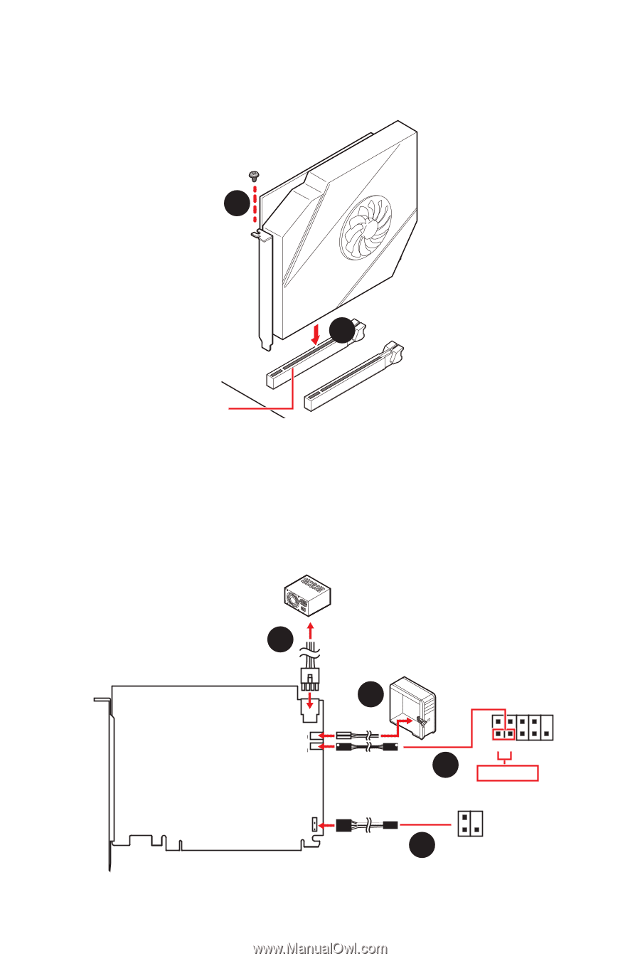
9. Insert the card into the PCI_E2 slot. 10. Use a screw to secure the card. 10 9 PCI_E2 11. Connect the PCIE_PWR1 to the power supply. 12. Connect the case's HDD LED cable to the JCASE connector. 13. Using the supplied HDD LED cable to connect the JMB connector and JFP1's HDD pins (pin 1 & pin3). 14. Using the supplied JSMB cable to connect the JSMB connector on the card and JSMB1 connector on the motherboard. And then you can set the fan duty cycle and the LED color of the card in BIOS. 11 PCIE_PWR1 JCASE + JMB + JSMB 12 JFP1 2 1 13 HDD LED 14 JSMB1 + - Overview of Components 41
-
 1
1 -
2
-
3
-
4
-
5
-
6
-
7
-
8
-
9
-
10
-
11
-
12
-
13
-
14
-
15
-
16
-
17
-
18
-
19
-
20
-
21
-
22
-
23
-
24
-
25
-
26
-
27
-
28
-
29
-
30
-
31
-
32
-
33
-
34
-
35
-
 36
36 -
 37
37 -
 38
38 -
 39
39 -
 40
40 -
 41
41 -
 42
42 -
 43
43 -
 44
44 -
 45
45 -
 46
46 -
47
-
48
-
49
-
50
-
51
-
52
-
53
-
54
-
55
-
56
-
57
-
58
-
59
-
60
-
61
-
62
-
63
-
64
-
65
-
66
-
67
-
68
-
69
-
70
-
71
-
72
-
73
-
74
 |
 |
41
Overview of Components
9.
Insert the card into the
PCI_E2
slot.
10.
Use a screw to secure the card.
11.
Connect the PCIE_PWR1 to the power supply.
12.
Connect the case’s HDD LED cable to the JCASE connector.
13.
Using the supplied HDD LED cable to connect the JMB connector and JFP1’s HDD
pins (pin 1 & pin3).
14.
Using the supplied JSMB cable to connect the JSMB connector on the card and
JSMB1 connector on the motherboard. And then you can set the fan duty cycle and
the LED color of the card in BIOS.
9
10
PCI_E2
+
+
11
12
13
14
1
2
+
-
HDD LED
JFP1
JSMB1
PCIE_PWR1
JCASE
JMB
JSMB