MSI MEG X570S ACE MAX User Manual - Page 42
SATA1~8: SATA 6Gb/s Connectors, JFP1, JFP2: Front Panel Connectors, Power Switch
 |
View all MSI MEG X570S ACE MAX manuals
Add to My Manuals
Save this manual to your list of manuals |
Page 42 highlights
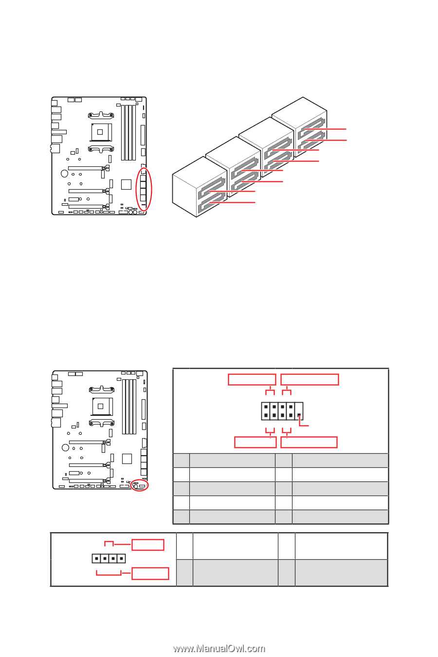
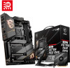
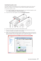
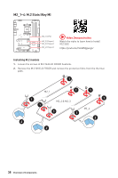
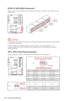
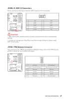
SATA1~8: SATA 6Gb/s Connectors These connectors are SATA 6Gb/s interface ports. Each connector can connect to one SATA device. SATA6 SATA5 SATA8 SATA7 SATA2 SATA1 SATA4 SATA3 ⚠⚠Important ∙∙Please do not fold the SATA cable at a 90-degree angle. Data loss may result during transmission otherwise. ∙∙SATA cables have identical plugs on either sides of the cable. However, it is recommended that the flat connector be connected to the motherboard for space saving purposes. JFP1, JFP2: Front Panel Connectors These connectors connect to the switches and LEDs on the front panel. Power LED Power Switch - -+ -- ++ JFP1 2 1 + 10 9 Reserved HDD LED Reset Switch 1 HDD LED + 2 3 HDD LED - 4 5 Reset Switch 6 7 Reset Switch 8 9 Reserved 10 Power LED + Power LED Power Switch Power Switch No Pin JFP2 1 + - + Buzzer 1 Speaker - 2 Speaker 3 Buzzer - 4 Buzzer + Speaker + 42 Overview of Components
-
 1
1 -
2
-
3
-
4
-
5
-
6
-
7
-
8
-
9
-
10
-
11
-
12
-
13
-
14
-
15
-
16
-
17
-
18
-
19
-
20
-
21
-
22
-
23
-
24
-
25
-
26
-
27
-
28
-
29
-
30
-
31
-
32
-
33
-
34
-
35
-
36
-
 37
37 -
 38
38 -
 39
39 -
 40
40 -
 41
41 -
 42
42 -
 43
43 -
 44
44 -
 45
45 -
 46
46 -
 47
47 -
48
-
49
-
50
-
51
-
52
-
53
-
54
-
55
-
56
-
57
-
58
-
59
-
60
-
61
-
62
-
63
-
64
-
65
-
66
-
67
-
68
-
69
-
70
-
71
-
72
-
73
-
74
 |
 |