MSI X299 SLI PLUS User Manual - Page 18
Back Panel, Connectors, Internal Connectors, Internal Buttons, Switches, Jumper, Debug LED
 |
View all MSI X299 SLI PLUS manuals
Add to My Manuals
Save this manual to your list of manuals |
Page 18 highlights
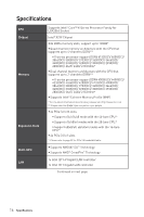
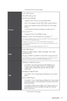
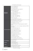
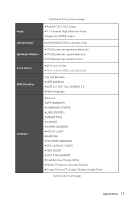
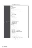
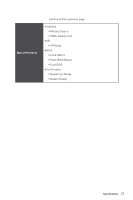
Continued from previous page Back Panel Connectors y 1x Clear CMOS button y 1x Flash BIOS Button y 1x PS/2 keyboard/ mouse combo port y 4x USB 2.0 Type-A ports ƒ 1x Flash BIOS port y 4x USB 3.1 Gen1 Type-A ports y 2x LAN (RJ45) ports y 1x USB 3.1 Gen2 Type-A port y 1x USB 3.1 Gen2 Type-C port y 5x OFC audio jacks y 1x Optical S/PDIF OUT connector Internal Connectors Internal Buttons y 1x 24-pin ATX main power connector y 1x 8-pin ATX 12V power connector y 8x SATA 6Gb/s connectors y 2x USB 2.0 connectors (supports additional 4 USB 2.0 ports) y 2x USB 3.1 Gen1 connectors (supports additional 4 USB 3.1 Gen1 ports) y 1x USB 3.1 Gen2 Type-C port y 1x 4-pin CPU fan connector y 1x 4-pin Water Pump connector y 4x 4-pin system fan connectors y 2x Front panel connectors y 1x Front panel audio connector y 1x RGB LED connector y 1x TPM module connector y 1x Virtual RAID on CPU connector y 1x Thunderbolt add-on card connector y 1x Power button y 1x Reset button Switches Jumper Debug LED y 1x Multi-BIOS switch y 1x Clear CMOS jumper y 1x Chassis Intrusion connector y 1x 2-Digit Debug Code LED 18 Specifications Continued on next page
-
 1
1 -
2
-
3
-
4
-
5
-
6
-
7
-
8
-
9
-
10
-
11
-
12
-
 13
13 -
 14
14 -
 15
15 -
 16
16 -
 17
17 -
 18
18 -
 19
19 -
 20
20 -
 21
21 -
 22
22 -
 23
23 -
24
-
25
-
26
-
27
-
28
-
29
-
30
-
31
-
32
-
33
-
34
-
35
-
36
-
37
-
38
-
39
-
40
-
41
-
42
-
43
-
44
-
45
-
46
-
47
-
48
-
49
-
50
-
51
-
52
-
53
-
54
-
55
-
56
-
57
-
58
-
59
-
60
-
61
-
62
-
63
-
64
-
65
-
66
-
67
-
68
-
69
-
70
-
71
-
72
-
73
-
74
-
75
-
76
-
77
-
78
-
79
-
80
-
81
-
82
-
83
-
84
-
85
-
86
-
87
-
88
-
89
-
90
-
91
-
92
-
93
-
94
-
95
-
96
-
97
-
98
-
99
-
100
-
101
-
102
-
103
-
104
-
105
-
106
-
107
-
108
-
109
-
110
 |
 |
