MSI X79A User Guide - Page 43
Memory channel A and B voltage. Refer to DDR_C/D.
 |
View all MSI X79A manuals
Add to My Manuals
Save this manual to your list of manuals |
Page 43 highlights
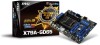
Chapter 1 BATT + MS-7760 Voltage Check Point Lite These voltage checkpoint are used to measure the current system voltages. A multimeter (not included) will be required to check voltages. To check the voltage, set the voltmeter switch to "DC", put the positive lead (red) on the postivtive point of the voltage source point and the negative lead (black) on the GND (ground) point. The following table describes the voltage check points. PCH_1P1V DDR_C/D DDR_A/B CPU_SA CPU_IO CPU_CORE GND Point PCH_1P1V DDR_C/D DDR_A/B CPU_SA CPU_IO CPU_CORE GND Description PCH 1.1 voltage. The PCH voltage is the voltage supplied to the Platform Controller Hub. Memory channel C and D voltage. The DDR memory voltage is the voltage supplied to the DDR memory modules on the mainboard. Lower memory timings may require higher voltages to maintain system stability. Memory channel A and B voltage. Refer to DDR_C/D. CPU system agent voltage (iMC). The CPU SA voltage is the voltage supplied to the IMC (Integrated Memory Controller) on the CPU. Higher overclocks may require a higher CPU SA voltage to maintain stability. CPU IO voltage (Uncore). The CPU IO voltage is the voltage supplied to the Uncore on the CPU. Higher overclocks may require a higher CPU IO voltage to maintain stability. CPU core voltage. The CPU core voltage is the voltage supplied to the CPU core. Higher overclocks may require higher CPU core voltages to maintain stability. Ground 1-33
-
 1
1 -
2
-
3
-
4
-
5
-
6
-
7
-
8
-
9
-
10
-
11
-
12
-
13
-
14
-
15
-
16
-
17
-
18
-
19
-
20
-
21
-
22
-
23
-
24
-
25
-
26
-
27
-
28
-
29
-
30
-
31
-
32
-
33
-
34
-
35
-
36
-
37
-
 38
38 -
 39
39 -
 40
40 -
 41
41 -
 42
42 -
 43
43 -
 44
44 -
 45
45 -
 46
46 -
 47
47 -
 48
48 -
49
-
50
-
51
-
52
-
53
-
54
-
55
-
56
-
57
-
58
-
59
-
60
-
61
-
62
-
63
-
64
-
65
-
66
-
67
-
68
-
69
-
70
-
71
-
72
-
73
-
74
-
75
-
76
-
77
-
78
-
79
-
80
-
81
-
82
-
83
-
84
-
85
-
86
-
87
-
88
-
89
-
90
 |
 |
