MSI Z68A User Guide - Page 32
TPM Module connector: JTPM1, S/PDIF-Out Connector: JSP1
 |
View all MSI Z68A manuals
Add to My Manuals
Save this manual to your list of manuals |
Page 32 highlights
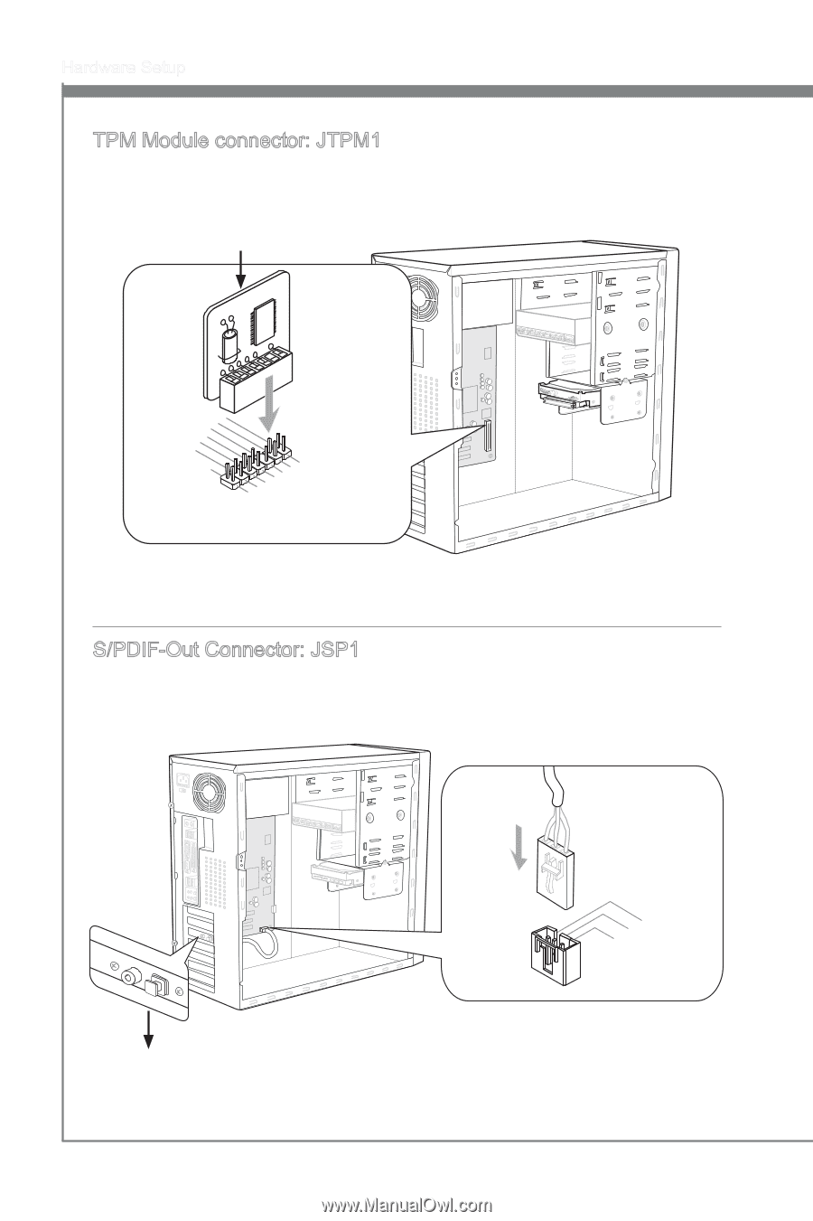
Hardware Setup TPM Module connector: JTPM1 This connector connects to a TPM (Trusted Platform Module) module (optional). Please refer to the TPM security platform manual for more details and usages. TPM module is optional 115V 2.34V.36S..3tS8aVe.n15Prd0iVaob1.NlwyP2I1o.eRopG4rwoPQ.rwGeionreurornudnd 1.L3P.L5CP.LCC7P.loLRC9cP.eLka1CsPd1e1ad.CtL3drPea.dLsdCrPsedasCr&edsFdsd&sraraedt&amsasdpteaa&intpa0dinap1tian2pin3 * The MB layout in this figure is for reference only. S/PDIF-Out Connector: JSP1 This connector is used to connect S/PDIF (Sony & Philips Digital Interconnect Format) interface for digital audio transmission. 115V 3.V2C.S1C.PGDrIoFund * The MB layout in this figure is for reference only. S/PDIF-Out Bracket (optional) 2-16
-
 1
1 -
2
-
3
-
4
-
5
-
6
-
7
-
8
-
9
-
10
-
11
-
12
-
13
-
14
-
15
-
16
-
17
-
18
-
19
-
20
-
21
-
22
-
23
-
24
-
25
-
26
-
 27
27 -
 28
28 -
 29
29 -
 30
30 -
 31
31 -
 32
32 -
 33
33 -
 34
34 -
 35
35 -
 36
36 -
 37
37 -
38
-
39
-
40
-
41
-
42
-
43
-
44
-
45
-
46
-
47
-
48
-
49
-
50
-
51
-
52
-
53
-
54
-
55
-
56
-
57
-
58
-
59
-
60
-
61
-
62
-
63
-
64
-
65
-
66
-
67
-
68
-
69
-
70
-
71
-
72
-
73
-
74
-
75
-
76
-
77
-
78
-
79
-
80
-
81
-
82
-
83
-
84
 |
 |
2-16
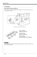
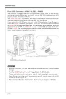
Hardware Setup
TPM Module connector: JTPM1
Th±s connector connects to a TPM (Trusted Platform Module) module (opt±onal). Please
refer to the TPM secur±ty platform manual for more deta±ls and usages.
* The MB layout ±n th±s figure ±s for reference only.
10.No Pin
14.Ground
8.5V Power
12.Ground
6.Serial IRQ
4.3.3V Power
2.3V Standby power
1.LPC Clock
3.LPC Reset
5.LPC address & data pin0
7.LPC address & data pin1
9.LPC address & data pin2
11.LPC address & data pin3
13.LPC Frame
TPM module ±s opt±onal
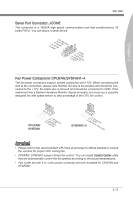
S/PDIF-Out Connector: JSP1
Th±s connector ±s used to connect S/PDIF (Sony & Ph±l±ps D±g±tal Interconnect Format)
±nterface for d±g±tal aud±o transm±ss±on.
3.VCC
2.SPDIF
1.Ground
* The MB layout ±n th±s figure ±s for reference only.
S/PDIF-Out Bracket (opt±onal)