Mackie Onyx 1220i Owner's Manual - Page 32
Block Diagram - logic
 |
View all Mackie Onyx 1220i manuals
Add to My Manuals
Save this manual to your list of manuals |
Page 32 highlights
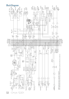
32 Onyx 1220i 48V Mono Channels 1-4 Mic Line Mic Ch 1-2 Line Hi-Z Input from FW 1 ret (Ch.11-12 only) L Stereo Channels 5-12 R Input from FW 2 ret (Ch.11-12 only) Phantom Insert + - Bypass Low Cut Gain Mic: 0 ~ +60dB Line: -20 ~ +40dB 75Hz HPF + - Line Hi-Z Line FW (Ch.11-12 only) Gain -20 ~ +20dB 3-Band EQ LO MID HI 80 100~8K 12K Mod Pt Pre Post FW Tap To FW Mod Pt PK -20 Main L/R Alt 3/4 Pan Level Aux Sends Mod Pt PK -20 3-Band EQ LO MID HI 80 2.5K 12K LO MID HI 80 2.5K 12K Pre Post To FW Mod Pt FW Tap To FW Mod Pt Solo Level Pan Main L/R Alt 3/4 Mod Pt Solo L Aux Return 1 R L Aux Return 2 R Level to Main L/R to Aux1 Level Internal Talkback mic Talkback Level Talkback Assign to Phones to Aux1-2 NOTE: Switches are shown in the default (out) position. NOTE: Modifications (marked MOD above) must be undertaken by authorized LOUD service centers only Main R L R L Main R/4 L/3 Alt R/4 Alt L/3 Aux 1 (pre) Aux 1 (pre) Aux 1 (post) Aux 1 (post) Aux 2 (pre) Aux 2 (pre) Aux 2 (post) Aux 2 (post) Solo(PFL) Solo(PFL) SoloLogic SoloLogic L sum Main level R sum +4dBu Mic level Alt L/3 sum Alt R/4 sum L CD/Tape in R Solo sum C/R Source Alt3/4 CD/Tape RUDE SOLO LED Main C/R L C/R R Meter C/R dim Control Room level off C/R to Main Solo logic FW 1-2 to Ch 11-12 off Firewire1-2 to C/R Tape Bal/Unbal Left Bal Main Out Bal Right Bal/Unbal Tape Left/3 Alt out Right/4 Control Room Out L R Phones level Phones Firewire I/O Aux 1 Aux 1 sum pre post Aux 2 Aux 2 sum pre post Aux 1 level Aux 2 level Channel 1-12 direct outs FW 15-16 FW 1-12 Firewire outputs FW 13-14 Aux 1 Out Aux 2 Out Block Diagram
-
 1
1 -
2
-
3
-
4
-
5
-
6
-
7
-
8
-
9
-
10
-
11
-
12
-
13
-
14
-
15
-
16
-
17
-
18
-
19
-
20
-
21
-
22
-
23
-
24
-
25
-
26
-
 27
27 -
 28
28 -
 29
29 -
 30
30 -
 31
31 -
 32
32 -
 33
33 -
 34
34 -
 35
35 -
 36
36 -
 37
37 -
38
-
39
-
40
-
41
 |
 |
