Mackie Onyx 1620i Owner's Manual - Page 7
Hookup Diagrams - mixer
 |
View all Mackie Onyx 1620i manuals
Add to My Manuals
Save this manual to your list of manuals |
Page 7 highlights
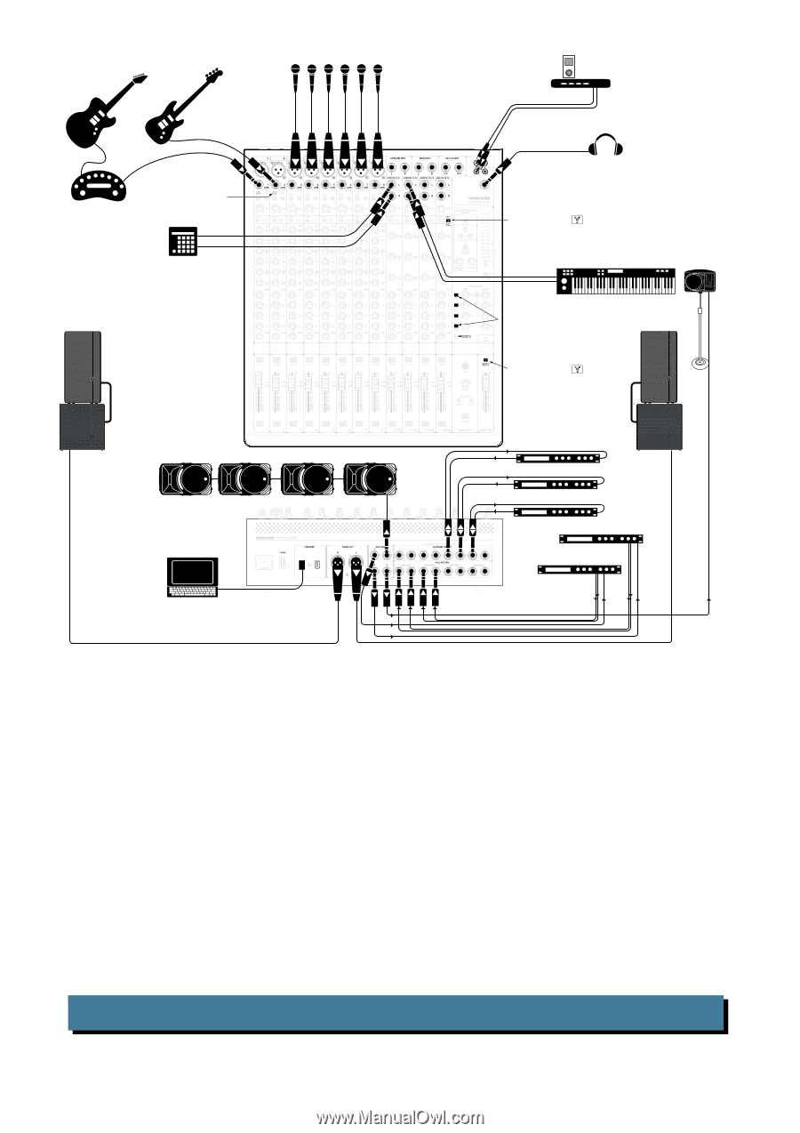
Hookup Diagrams Microphones Electric Guitar Bass Guitar iPod Docking Station Amplifier Modeler Drum Machine press HI-Z button 48V 48V 48V 48V 48V 48V 48V 48V Headphones press FW button ( ) to send FW 1-2 computer output into mixer channels 15-16 Keyboard SRM150 Powered Monitor for keyboard player (Aux Send 2) HD1531 Powered Speaker Main Right HD1801 Powered Subwoofer MUTE MUTE MUTE MUTE MUTE MUTE MUTE MUTE MUTE MUTE MUTE MUTE SOLO SOLO SOLO SOLO SOLO SOLO SOLO SOLO SOLO SOLO SOLO SOLO Mackie SRM450v2 Powered Speakers (Stage Monitors) Aux Send 1 Laptop Computer with audio production software Set Aux 1, 2 PRE for monitors Set Aux 3, 4 POST for external processors press FW button ( HD1531 Powered Speaker Main Left ) to send main mix to computer via FireWire channels 15 and 16 HD1801 Powered Subwoofer Send Return Compressor (Vocals) Send Return Compressor (Vocals) Send Return Dynamics Processor (Bass) Delay (Aux Send 4) Reverb (Aux Send 3) This diagram shows an electric guitar connected to the channel 1 line input via an amplifier modeler, a bass guitar connected directly to channel 2 (hi-z switch in), microphones connected to the channel 3-8 mic inputs, a drum machine connected to the channel 9-10 stereo line inputs, and a keyboard connected to the channel 11-12 stereo line inputs. An iPod® dock connects to the tape inputs. A dynamics processor is connected to the insert jack of channel 2 to work its magic on your bass. Vocal compressors are connected to the channel 3 and 4 inserts. A reverb unit receives a mono input from the aux 3 send (in post-fader mode), and its stereo outputs connect to the stereo aux 3 return inputs. A delay processor receives a mono input from the aux 4 send (in post-fader mode), and its stereo outputs connect to the stereo aux 4 return inputs. A plethora of SRM450v2 powered speakers are strewn across the stage as monitors for the band; they are connected to the aux 1 send jack (in pre-fader mode). A Mackie SRM150 powered speaker is connected to aux send 2 as a monitor for the keyboard player. Aux 2 is set to pre-fader using the Aux 2 pre/post switch in the Aux Master section. Headphones are used to monitor levels. The club is driven by connecting a pair of HD1801 powered subwoofers and a pair of HD1531 powered speakers to the main left and right outputs. A laptop computer connects to a FireWire port, allowing the 2-channel main mix, individual channels, and the aux sends to be recorded. Two channels can be played back from your audio production software. These can enter as either a source for the control room and phones, or channels 15 and 16. Typical Club System Owner's Manual 7
-
 1
1 -
 2
2 -
 3
3 -
 4
4 -
 5
5 -
 6
6 -
 7
7 -
 8
8 -
 9
9 -
 10
10 -
 11
11 -
 12
12 -
13
-
14
-
15
-
16
-
17
-
18
-
19
-
20
-
21
-
22
-
23
-
24
-
25
-
26
-
27
-
28
-
29
-
30
-
31
-
32
-
33
-
34
-
35
-
36
-
37
-
38
-
39
-
40
 |
 |