Mackie Onyx 1640i Owner's Manual - Page 11
Line Inputs, Insert, Mic Inputs, Phantom Power
 |
View all Mackie Onyx 1640i manuals
Add to My Manuals
Save this manual to your list of manuals |
Page 11 highlights
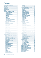
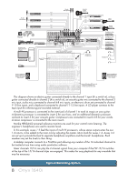
4. MIC INPUTS This is a female XLR connector, that accepts a balanced microphone input from almost any type of microphone. The microphone preamps feature our Onyx design, with higher fidelity and headroom rivaling any standalone mic preamp on the market today. The XLR inputs are wired as follows: Pin 1 = Shield or ground Pin 2 = Positive (+ or hot) Pin 3 = Negative (- or cold) We use phantom-powered, balanced microphone inputs just like the big studio mega-consoles, for exactly the same reason: This kind of circuit is excellent at rejecting hum and noise. You can plug in almost any kind of mic that has a standard XLR-type male mic connector. Professional ribbon, dynamic, and condenser mics all sound excellent through these inputs. The mic inputs will handle any kind of mic level you can toss at them, without overloading. Microphone-level signals are passed through the mixer's splendid microphone preamplifiers to become line-level signals. See Appendix B (page 29) for further details and some rather lovely drawings of the connectors you can use with your mixer. PHANTOM POWER Most modern professional condenser mics require 48V phantom power, which lets the mixer send low-current DC voltage to the mic's electronics through the same wires that carry audio. (Semi-pro condenser mics often have batteries to accomplish the same thing.) "Phantom" owes its name to an ability to be "unseen" by dynamic mics (Shure SM57/SM58, for instance), which don't need external power and aren't affected by it anyway. Phantom power for each channel can be selected using that channel's phantom [22] switch. 5. LINE INPUTS These 1/4" jacks share circuitry (but not phantom power) with the mic preamps, and can be driven by balanced or unbalanced sources. To connect balanced lines to these inputs, use a 1⁄4" Tip-Ring-Sleeve (TRS) plug, wired as follows: Tip = Positive (+ or hot) Ring = Negative (- or cold) Sleeve = Shield or ground To connect unbalanced lines to these inputs, use a 1⁄4" mono (TS) phone plug, wired as follows: Tip = Positive (+ or hot) Sleeve = Shield or ground These line-level inputs can also accept instrumentlevel signals if the hi-z switches [25] are pressed in. This allows you to connect guitars directly to channels 1 and 2, without the need for a DI box. The input impedance is optimized for direct connection, and high-frequency fidelity is assured. 6. INSERT These unbalanced 1/4" jacks are for connecting serial effects processors such as compressors, equalizers, de-essers, or filters. The insert point is after the gain control [26] and low cut filter [23], but before the channel's EQ [29-34] and level [38]. The channel signal can go out of the insert jack to an external device, be processed and come back in on the same insert jack. To do this requires a standard insert cable that must be wired thusly: Tip = send (output to effects device) Ring = return (input from effects device) Sleeve = common ground ring tip sleeve (TRS plug) SEND to processor "tip" This plug connects to one of the mixer's Channel Insert jacks. "ring" RETURN from processor Never plug single-ended (unbalanced) microphones, or ribbon mics into the mic input jacks if phantom power is on. Do not plug instrument outputs into the mic XLR input jacks with phantom power on, unless you are certain it is safe. Insert jacks can be used as channel direct outputs; post-gain, and pre-EQ. See the connector section on page 30 (figure G) showing three ways to use insert cables. Owner's Manual 11
-
 1
1 -
2
-
3
-
4
-
5
-
 6
6 -
 7
7 -
 8
8 -
 9
9 -
 10
10 -
 11
11 -
 12
12 -
 13
13 -
 14
14 -
 15
15 -
 16
16 -
17
-
18
-
19
-
20
-
21
-
22
-
23
-
24
-
25
-
26
-
27
-
28
-
29
-
30
-
31
-
32
-
33
-
34
-
35
-
36
-
37
-
38
-
39
-
40
-
41
-
42
-
43
-
44
-
45
-
46
-
47
-
48
-
49
-
50
 |
 |