Magic Chef MCSRE24S User Manual - Page 12
Installation Instructions
 |
View all Magic Chef MCSRE24S manuals
Add to My Manuals
Save this manual to your list of manuals |
Page 12 highlights
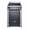
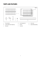
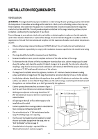
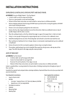
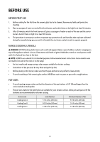
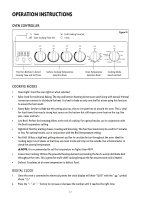
INSTALLATION INSTRUCTIONS UNPACKING & INSTALLING LEVELING FEET AND BACK PANEL WARNING: Excessive Weight Hazard / Tip Over Hazard • A child or adult can tip the range and be killed. • Use two or more people to move and install range. • Failure to follow these instructions can result in death or serious burns to children and adults. 1. Remove shipping materials from the range. DO NOT remove protective film covering the appliance. DO NOT remove tape securing the drawer. 2. Remove oven racks and parts package from the inside oven. 3. Remove the four (4) L-shaped cardboard corners from the carton. Stack one cardboard corner on top of another. Repeat with the other 2 corners. 4. Place the cardboard stacks on the floor behind the range to support the range when it is laid on its back. 5. Using 2 or more people firmly grasp the range and gently lay it on its back on the cardboard corners. 6. Install the leveling feet one at a time. The leveling feet can be found in a box that was inside the oven. 7. Place cardboard or hardboard in front of range. Using 2 or more people, stand range back up onto cardboard or hardboard. 8. Remove the protective film covering the appliance. Remove tape securing the drawer. 9. The stainless steel back panel can now be installed. Place panel into the grooves on the top rear of the range. Then affix the panel to the range using the screws provided. ANTI-TIP BRACKET WARNING: Tip Over Hazard • A child or adult can tip the range and be killed. • Connect anti-tip bracket to rear range foot. • Reconnect the anti-tip bracket, if the range is moved. • Failure to follow these instructions can result in death or serious burns to children and adults. Contact a qualified floor covering installer for the procedure of drilling mounting holes through your type of floor covering. Assemble the required tools and parts before starting installation. Read and follow the instructions provided with any tools listed here. Tools Needed for Installation • Hand or Electric Drill • Drill Bit • Concrete / Ceramic Floors: 3/16" (4.6 mm) Masonry Drill Bit • Wood Floors: 1/8" (3.2 mm) Drill Bit • Flat-Blade Screwdriver • Hammer • Measuring Tape • Masking Tape Parts Supplied for Installation a. Anti-Tip Bracket (1) b. Plastic Anchors (2) c. Screws (2) Figure 4 a b c 12
-
 1
1 -
2
-
3
-
4
-
5
-
6
-
 7
7 -
 8
8 -
 9
9 -
 10
10 -
 11
11 -
 12
12 -
 13
13 -
 14
14 -
 15
15 -
 16
16 -
 17
17 -
18
-
19
-
20
-
21
-
22
-
23
-
24
-
25
-
26
-
27
-
28
-
29
-
30
-
31
-
32
-
33
-
34
-
35
-
36
-
37
-
38
-
39
-
40
-
41
-
42
-
43
-
44
-
45
-
46
-
47
-
48
-
49
-
50
-
51
-
52
 |
 |