Magic Chef MCSRE24S User Manual - Page 13
Electrical Connection
 |
View all Magic Chef MCSRE24S manuals
Add to My Manuals
Save this manual to your list of manuals |
Page 13 highlights
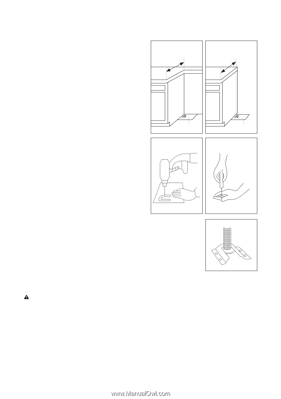
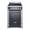
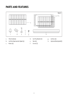
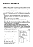
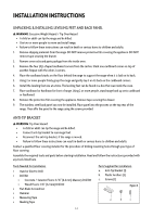
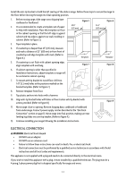
Install the anti-tip bracket to hold the left rear leg of the slide-in range. Follow these steps to secure the range to the floor before moving the range into final operating position. 1. Before moving range, slide range onto shipping base cardboard or hardboard. 2. It is recommended to create a template out of paper to help with installation. Place this template on floor in the cabinet opening so that the left edge is against cabinet and top edge is against rear wall, molding or cabinet. (Refer to Figure 5.) 25.0" (635 mm) Figure 5 25.0" (635 mm) Figure 6 3. Tape template in place. 4. If countertop is deeper than 25" (635 mm), measure and mark a distance of 25" (635 mm) in from front of countertop and align template with mark. (Refer to Figure 6.) Template Template 5. If countertop is not flush with cabinet opening edge, align template with overhang. Figure 7 Figure 8 6. If cabinet opening is wider than specified in Installation Instructions, adjust template so range will be centered in cabinet opening. 7. To mount anti-tip bracket to wood floor, drill two 1/8" (3.2 mm) holes at the positions marked on the bracket template. (Refer to Figure 7.) 8. Remove template from floor. 9. Tap plastic anchors into holes with a hammer. 10. Align anti-tip bracket holes with holes in floor. Fasten anti-tip bracket with screws provided. (Refer to Figure 8.) Figure 9 11. Move range close to opening. Remove shipping base, cardboard or hardboard from under range. Connect power supply cord as described in the "Electrical Connection" section on page 13. Move range into final position, making sure rear leveling leg slides into anti-tip bracket. (Refer to Figure 9.) 12. Continue installing your range following the installation Instructions. ELECTRICAL CONNECTION WARNING: Electrical Shock Hazard • Do not use an adapter. • Do not use an extension cord. • Failure to follow these instructions can result in death, fire, or electrical shock. • Electrical connection must be performed by a qualified service technician in accordance with the kit instructions and all local codes and requirements. This appliance is not supplied with a plug and needs to be connected directly to the electrical mains. If you wish to install this appliance with a plug, it must installed by a qualified technician. The plug must be a 4-prong, 3-phase power plug that is designed specifically for ranges and ovens. 13
-
 1
1 -
2
-
3
-
4
-
5
-
6
-
7
-
 8
8 -
 9
9 -
 10
10 -
 11
11 -
 12
12 -
 13
13 -
 14
14 -
 15
15 -
 16
16 -
 17
17 -
 18
18 -
19
-
20
-
21
-
22
-
23
-
24
-
25
-
26
-
27
-
28
-
29
-
30
-
31
-
32
-
33
-
34
-
35
-
36
-
37
-
38
-
39
-
40
-
41
-
42
-
43
-
44
-
45
-
46
-
47
-
48
-
49
-
50
-
51
-
52
 |
 |