Magnavox 37MF331D User Manual - Page 28
Connect Accessory Devices, Recorder VCR-DVD+RW, Don't insert any cable here. This area is for,
 |
View all Magnavox 37MF331D manuals
Add to My Manuals
Save this manual to your list of manuals |
Page 28 highlights
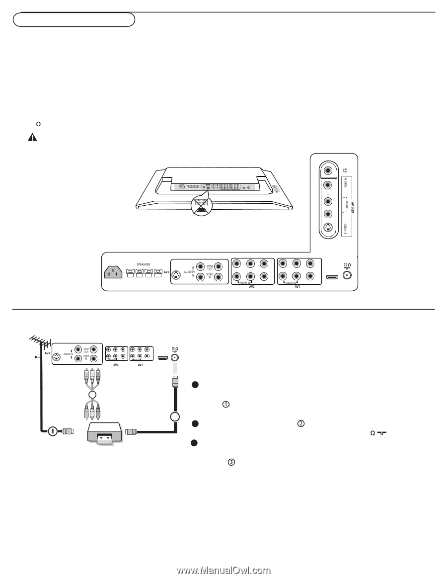
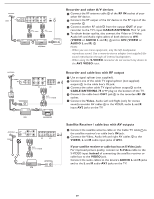
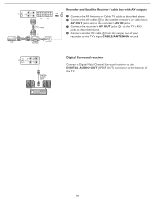
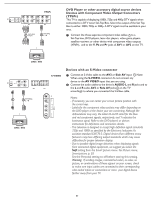
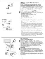
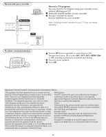
Connect Accessory Devices There is a wide range of audio and video devices that can be connected to your TV.The following connection diagrams show you how to connect them to the TV. AV1 YPbPr, VIDEO and L/R Audio, AV2 YPbPr, VIDEO and L/R Audio, AV3 VIDEO, S-VIDEO, L/R Audio and Digital Audio out (SPDIF OUT) SIDE VIDEO, S-VIDEO and L/R Audio, Headphone SPEAKERS HDMI 75 Don't insert any cable here. This area is for repair center use only. AC IN AC IN S-VIDEO Pr Pb Y Pb Y L HDMI R L R VIDEO L R VIDEO VIDEO L R S-VIDEO VIDEO L R S-VIDEO L S-VIDEO R Pr Pb Y Pr L R VIDEO L Pb Y HDMI R VIDEO ANTENNA CABLE S-VIDEO Recorder (VCR-DVD+RW) Note: Do not place your recorder too close to the TV screen. Some L Pr Pb Y Pr Pb Y HDMI recorders may be susceptible for signals from the display. Keep recorders L R VIDEO L R VIDEO R a minimum distance of 20" from the screen. AV3: 3 L + R + VIDEO OUT IN OUT 1 Connect the RF Antenna or Cable TV cable (eventually through an optional two-way signal splitter and/or Cable TV converter box) to the RF IN socket of your 2 recorder. 2 Connect another RF cable from the output OUT of your recorder to the TV's CABLE/ANTENNA 75 jack. 3 For better playback quality for stereo device only, also connect the Video, Audio Left and Right (only for stereo devices) AV cables to the VIDEO, AUDIO L and R input jacks of AV3. If your recorder has an S-VHS video jack: For improved picture quality, connect an S-video cable to the S-VIDEO input instead of connecting the recorder to the VIDEO jack of AV3. S-Video does not provide audio, so audio cables must still be connected to provide sound. 28
-
 1
1 -
2
-
3
-
4
-
5
-
6
-
7
-
8
-
9
-
10
-
11
-
12
-
13
-
14
-
15
-
16
-
17
-
18
-
19
-
20
-
21
-
22
-
 23
23 -
 24
24 -
 25
25 -
 26
26 -
 27
27 -
 28
28 -
 29
29 -
 30
30 -
 31
31 -
 32
32 -
 33
33 -
34
-
35
-
36
-
37
-
38
 |
 |