Magnavox 37MF331D User Manual - Page 31
YDVD Player or other accessory digital source devices RDevices with Component Video Output - stand
 |
View all Magnavox 37MF331D manuals
Add to My Manuals
Save this manual to your list of manuals |
Page 31 highlights
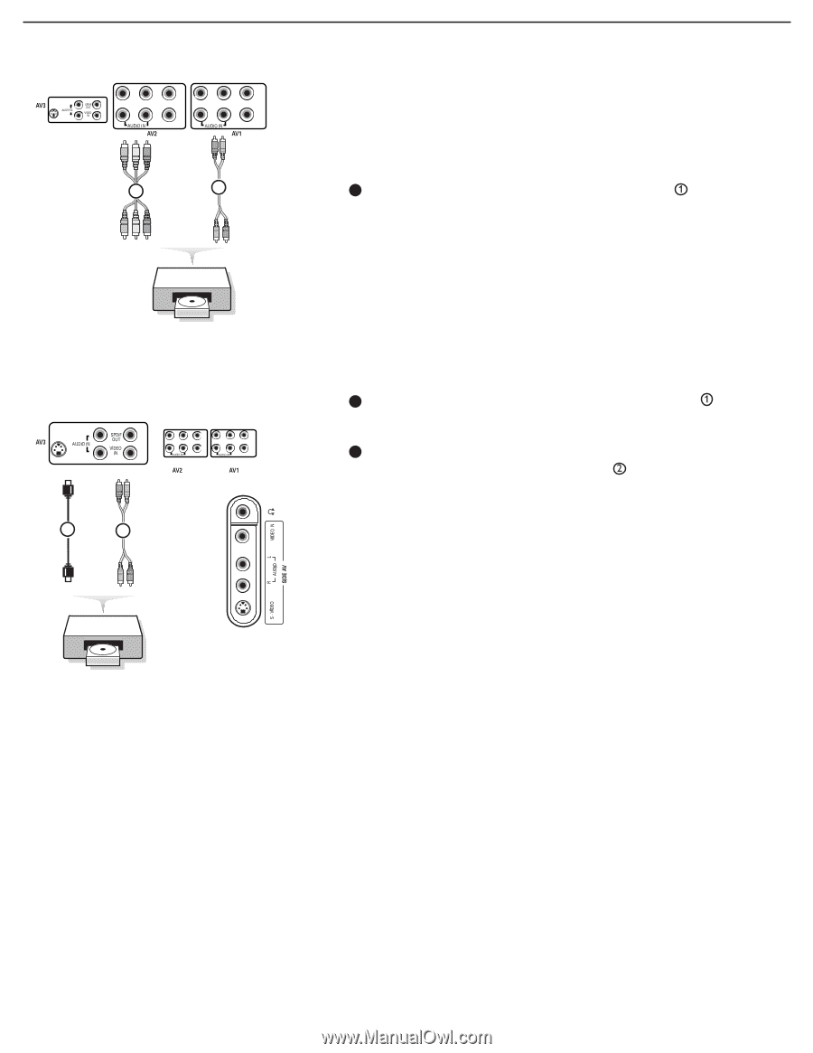
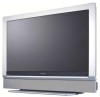
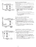
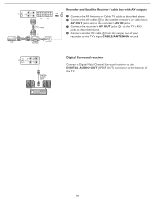
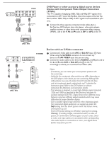
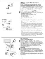
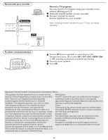
L S-VIDEO R Pr Pb Y L R VIDEO YPbPr Pr Pb Y L R VIDEO 1 AV1/AV2: YPbPr 2 AV1/AV2: L + R DVD Player or other accessory digital source devices Devices with Component Video Output Connectors (YPbPr) This TV is capable of displaying 1080i, 720p and 480p DTV signals when connected to a DTV tuner Set-Top Box. Select the output of the Set Top Box to either 1080i, 720p or 480p. A DTV signal must be available in your area. 1 Connect the three separate component video cables to a Set-Top box, DVD-players, laser-disc players, video game players, satellite receivers or other device with component video outputs (YPbPr), and to the Y, Pb and Pr jacks of AV1 or AV2 on the TV. DVD / STB L S-VIDEO R S-VIDEO Pr Pb Y L R VIDEO Pr Pb Y L R VIDEO 1 2 AV3/Side: L + R DVD / STB VIDEO L R S-VIDEO Devices with an S-Video connector 1 Connect an S-Video cable to the AV3 or Side AV input . Note: When using the S-VIDEO connector do not connect any device to the AV VIDEO input that you are using. 2 Connect the audio cables to the device's AUDIO L and R jacks and to the L and R audio AV3 or Side AV jacks on the TV accordingly to where you connected the S-Video cable. Notes: - If necessary, you can center your screen picture position with the cursor keys. - Labels for the component video sockets may differ depending on the DVD player or the device your are connecting. Although the abbreviations may vary, the letters B and R stand for the blue and red component signals, respectively, and Y indicates the luminance signal. Refer to the DVD player's or devices instructions for definitions and connection details. - This television is designed to accept high definition signal standards 720p and 1080i as specified by the Electronic Industries As sociation standard EIA770.3. Digital devices from different manu facturers may have differing output standards which may cause difficulties for proper television display. - Due to possible digital image distortion when displaying signals from connected digital equipment, we suggest you select the Soft setting from the Smart picture menu. See Picture menu, Smart picture, p. 20. Set the Personal setting to off before storing this setting. Warning: If scrolling images, mismatched colors, no color, no picture, or combinations of these appear on your screen, check to make sure input cables are connected to their corresponding color-coded inputs or connections or move your digital device farther away from your TV. 31
-
 1
1 -
2
-
3
-
4
-
5
-
6
-
7
-
8
-
9
-
10
-
11
-
12
-
13
-
14
-
15
-
16
-
17
-
18
-
19
-
20
-
21
-
22
-
23
-
24
-
25
-
 26
26 -
 27
27 -
 28
28 -
 29
29 -
 30
30 -
 31
31 -
 32
32 -
 33
33 -
 34
34 -
 35
35 -
 36
36 -
37
-
38
 |
 |