Magnavox 40MF401B Owners Manual - Page 9
Control Panel, Terminals, Side Panel, Rear Panel - no picture
 |
View all Magnavox 40MF401B manuals
Add to My Manuals
Save this manual to your list of manuals |
Page 9 highlights
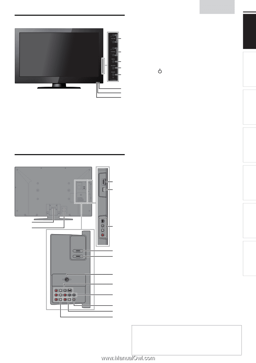
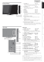
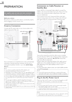
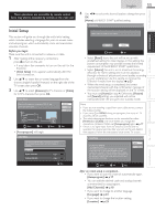
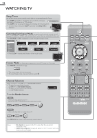
Control Panel Terminals 12 13 English 9 1 VOLUME + / − ➠ p.13 Press to adjust the volume up /down or move right (+) / left (−) through the main menu items. 1 2 CHANNEL + / − ➠ p.12 Press to select channels or move up (+) / down (−) 2 through the main menu items. 3 MENU ➠ p.15 3 4 SOURCE 4 ➠ p.12 5 5 POWER ➠ p.11 Press to turn the unit on and go into standby mode. To completely turn off the unit, you must unplug the AC 6 power cord. 7 6 Infrared sensor window 8 Receives infrared rays transmitted from the remote control. 7 Standby indicator Lights up red when the unit is in standby mode and flashes when the unit goes into standby mode. 8 Illuminance sensor window Alters the brightness of the TV screen automatically by detecting your room lighting level. Do not block anything in front of its window to work properly. Side Panel 9 HDMI 3 Input jack ➠ p.10, 25 10 USB terminal ➠ p.27 9 Use this terminal only to play back the JPEG picture file stored on a USB storage device, or when software 10 update is needed. 11 S-Video / Composite Video / Audio (L/R) Input jacks for VIDEO 2 ➠ p.26 Rear Panel 12 Cable management ➠ p.27 13 AC power cord Inlet ➠ p.10 11 14 HDMI 2 Input jack ➠ p.10, 25 15 HDMI 1 / HDMI-DVI Input jack ➠ p.10, 25, 27 HDMI connection for HDMI or DVI device. When you connect your PC that has a DVI terminal, you can enjoy this unit as a PC monitor. 14 15 16 Antenna Input jack ➠ p.10 17 S-Video / Composite Video / Audio (L/R) Input jacks for VIDEO 1 ➠ p.26 18 Component Video / Audio (L/R) 16 Input jacks ➠ p.10, 25 19 Digital Audio Output jack ➠ p.26 17 20 Analog Audio (L/R) Output jacks ➠ p.26 18 21 Analog Audio (L/R) Input jacks for HDMI-DVI Input jacks ➠ p.25, 27 19 Audio cable connection from a DVI device. 20 When you connect your PC that has a DVI terminal, use 21 a stereo mini plug conversion cable as well. (For HDMI 1 Input jack only) Note for USB terminal • User should not connect any devices to the USB terminal such as digital camera, keyboard, mouse, etc. (because these will not work). • The software update is, in most cases, handled by an authorized service person or in some circumstances the user may be asked to do the software update themselves. INFORMATION USEFUL TIPS WATCHING TV USING FUNCTIONS CONNECTING DEVICES PREPARATION INTRODUCTION
-
 1
1 -
2
-
3
-
 4
4 -
 5
5 -
 6
6 -
 7
7 -
 8
8 -
 9
9 -
 10
10 -
 11
11 -
 12
12 -
 13
13 -
 14
14 -
15
-
16
-
17
-
18
-
19
-
20
-
21
-
22
-
23
-
24
-
25
-
26
-
27
-
28
-
29
-
30
-
31
-
32
-
33
 |
 |