Marantz SR4003 SR4003 User Manual - Englis - Page 13

Connecting Speakers

Page 13 highlights

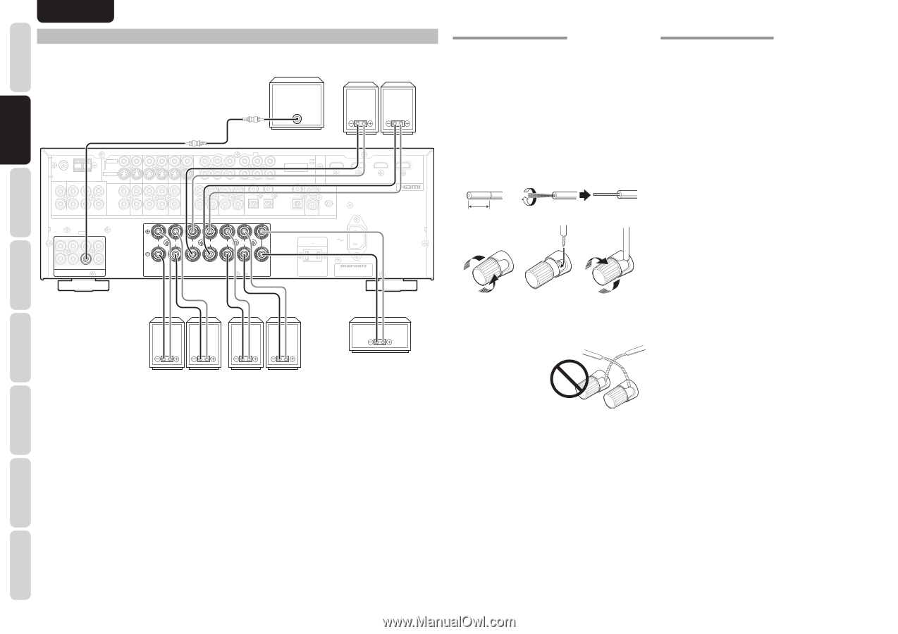
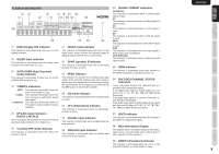
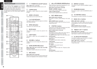
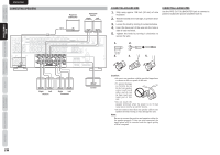
NAMES AND FUNCTIONS BASIC CONNECTIONS BASIC OPERATION ADVANCED CONNECTIONS ENGLISH CONNECTING SPEAKERS Powered subwoofer Surround BACK Right Left VIDEO FM (75Ω) GND AM ANTENNA L SL C L S-VIDEO TV SBL R R SR SW SBR (AUX 2) 7.1CH INPUT TV INPUT 1 INPUT DVD VCR IN VCR OUT DSS MONITOR OUT 2 Y CB/PB CR/PR Y DVD IN OUT VCR DSS AUDIO IN OUT TAPE IN OUT CD/CDR CB/PB INPUT 3 COMPONENT VIDEO MONITOR OUT CR/PR IN 3 4 INPUT 1 1 2 DIGITAL IN OPT OUT FLASHER DIGITAL OUT REMOTE CONT. IN INPUT 2 INPUT 3 OUTPUT L SL C SBL R L R L R L AC OUTLETS 120V 60Hz AC IN R SR SW SBR PRE OUT FRONT SURROUND BACK SURROUND S. SPEAKER B SPEAKER SYSTEMS : 6-8 OHMS CENTER SWITCHED 1.25A 150W MODEL NO. SR4003 Right Left Front A Right Left Surround Center CONNECTING SPEAKER WIRE 1. Strip away approx. 3/8 inch (10 mm) of wire insulation. 2. Twist the bared wire ends tight, to prevent short circuits. 3. Loosen the knob by turning it counterclockwise. 4. Insert the bare part of the wire into the hole in side of each terminal. 5. Tighten the knob by turning it clockwise to secure the wire. CONNECTING A SUBWOOFER Use the PRE OUT SUBWOOFER jack to connect a powered subwoofer (power amplifier built in). 1. 2. 3/8 inch 10 mm 3. 4. 5. Caution: • Be sure to use speakers with the specified impedance as shown on the rear panel of this unit. • To prevent damage to circuitry, do not let the bare speaker wires touch each other and do not let them touch any metal part of this unit. • Do not touch the speaker terminals when the power is on. It may cause you to receive an electric shocks. • Do not connect more than one speaker cable to one speaker terminal. Doing so may damage this unit. Note: Be sure to connect the positive and negative cables for the speaker properly. If they are miss-connected, the signal phase will be reversed and the signal quality will be corrupted. SETUP ADVANCED OPERATION TROUBLESHOOTING OTHERS 10

  • 1
  • 2
  • 3
  • 4
  • 5
  • 6
  • 7
  • 8
  • 9
  • 10
  • 11
  • 12
  • 13
  • 14
  • 15
  • 16
  • 17
  • 18
  • 19
  • 20
  • 21
  • 22
  • 23
  • 24
  • 25
  • 26
  • 27
  • 28
  • 29
  • 30
  • 31
  • 32
  • 33
  • 34
  • 35
  • 36
  • 37
  • 38
  • 39
  • 40
  • 41
  • 42
  • 43
  • 44
  • 45
  • 46
  • 47
  • 48

10
ENGLISH
BASIC
CONNECTIONS
BASIC OPERATION
ADVANCED
CONNECTIONS
SETUP
ADVANCED
OPERATION
TROUBLESHOOTING
OTHERS
NAMES AND
FUNCTIONS
BASIC
CONNECTIONS
CONNECTING A SUBWOOFER
Use the PRE OUT SUBWOOFER jack to connect a
powered subwoofer (power amplifier built in).
CONNECTING SPEAKERS
R
SR
SR
C
SW
SW
SBR
SBR
SL
SL
SBL
SBL
L
R
SPEAKER SYSTEMS : 6-8 OHMS
R
L
L
L
R
IN
IN
OPT
OPT
DIGITAL OUT
DIGITAL OUT
L
SL
SL
C
SBL
SBL
R
SR
SR
SW
SW
SBR
SBR
R
L
FM
FM
(
75
75
Ω
)
GND
GND
AM
AM
C
R
/
P
R
C
B
/
P
B
Y
ANTENNA
ANTENNA
DIGITAL IN
DIGITAL IN
OUT
OUT
IN
IN
CD/CDR
CD/CDR
OUT
OUT
IN
IN
TAPE
TAPE
VCR
VCR
DVD
DVD
TV
TV
AUDIO
AUDIO
DSS
DSS
IN
IN
OUT
OUT
C
R
/
P
R
C
B
/
P
B
Y
DSS
DSS
TV
TV
DVD
DVD
VCR IN
VCR IN
VCR OUT
VCR OUT
MONITOR OUT
MONITOR OUT
INPUT
INPUT
1
INPUT
INPUT
2
S-VIDEO
S-VIDEO
VIDEO
VIDEO
PRE OUT
PRE OUT
CENTER
CENTER
FRONT
FRONT
SURROUND BACK
SURROUND BACK
S. SPEAKER B
S. SPEAKER B
SURROUND
SURROUND
AC IN
AC IN
MONITOR
MONITOR
OUT
OUT
INPUT
INPUT
3
COMPONENT
COMPONENT
VIDEO
VIDEO
OUT
OUT
REMOTE CONT.
REMOTE CONT.
2
1
4
3
7.1CH INPUT
7.1CH INPUT
(
AUX 2
AUX 2
)
AC OUTLETS
AC OUTLETS
120V
60Hz
120V
60Hz
SWITCHED
SWITCHED
1.25A 150W
1.25A 150W
MODEL NO. SR4003
MODEL NO. SR4003
INPUT 3
INPUT 3
OUTPUT
OUTPUT
INPUT 2
INPUT 2
INPUT 1
INPUT 1
IN
IN
FLASHER
FLASHER
SW
SW
PRE OUT
PRE OUT
R
SPEAKER SYSTEMS : 6-8 OHMS
R
L
L
L
R
CENTER
CENTER
FRONT
FRONT
SURROUND BACK
SURROUND BACK
S. SPEAKER B
S. SPEAKER B
SURROUND
SURROUND
Powered
subwoofer
Surround
BACK
Center
Left
Surround
Right
Front A
Right
Left
Right
Left
CONNECTING SPEAKER WIRE
1.
Strip away approx. 3/8 inch (10 mm) of wire
insulation.
2.
Twist the bared wire ends tight, to prevent short
circuits.
3.
Loosen the knob by turning it counterclockwise.
4.
Insert the bare part of the wire into the hole in
side of each terminal.
5.
Tighten the knob by turning it clockwise to
secure the wire.
1.
2.
3.
4.
5.
3/8 inch
10 mm
Caution:
• Be sure to use speakers with the specified impedance
as shown on the rear panel of this unit.
• To prevent damage
to circuitry, do not
let the bare speaker
wires touch each
other and do not
let them touch any
metal part of this
unit.
• Do not touch the
speaker terminals when the power is on. It may
cause you to receive an electric shocks.
• Do not connect more than one speaker cable to one
speaker terminal. Doing so may damage this unit.
Note:
Be sure to connect the positive and negative cables for
the speaker properly. If they are miss-connected, the
signal phase will be reversed and the signal quality
will be corrupted.