Maytag MEDB765FW W10240504 - Page 12
Do Not Remove Or Destroy
 |
View all Maytag MEDB765FW manuals
Add to My Manuals
Save this manual to your list of manuals |
Page 12 highlights
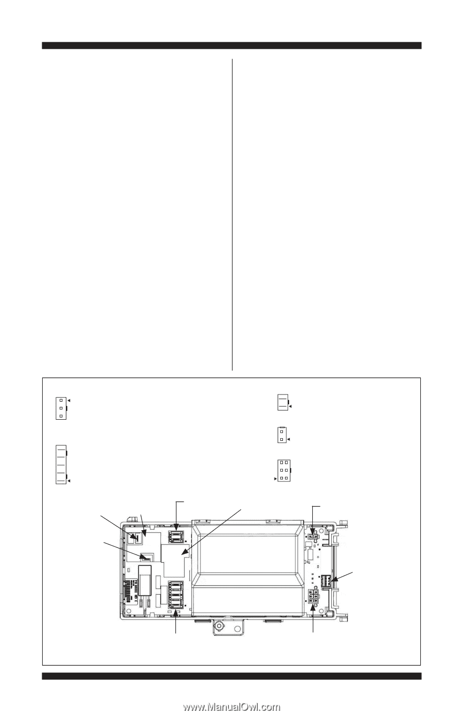
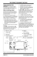
FOR SERVICE TECHNICIAN'S USE ONLY TROUBLESHOOTING TESTS IMPORTANT: The following procedures may require the use of needle probes to measure voltage. Failure to use needle probes will damage the connectors. TEST #1: ACU Power Check This test is used to determine if power is present at the machine control electronics. This test assumes that proper voltage is present at the outlet. 1. Unplug dryer or disconnect power. 2. Check for appropriate line voltages at the outlet: 240VAC (electric 2-phase), 208VAC (electric 3-phase), or 120VAC (gas). If line voltage is present, go to step 3. If line voltage is not present, check for tripped circuit breaker or blown household fuse. If CB (circuit breaker) is not tripped, have customer check with qualified electrician. 3. Remove console to access the machine electronics. 4. ACU VAC - With voltmeter set to AC, connect black probe to ACU P8-3 (N) and red probe to P9-2 (L1). (See Figure 2.) Plug in dryer or reconnect power. If 120VAC is present, unplug dryer or disconnect power and go to step 5. If 120VAC is not present, unplug dryer or disconnect power and perform TEST #2: Supply Connections, page 13. 5. ACU +5VDC - With voltmeter set to DC, unplug connector P2 from the ACU and connect black probe to ACU P2-3 (ground) and red probe to P2-1 (+5V DC). Plug in dryer or reconnect power. If +5VDC is present, go to step 8. If +5VDC is not present, go to step 6. 6. Unplug dryer or disconnect power. Unplug P14 from the ACU. Plug in dryer or reconnect power and repeat step 5. If +5VDC returns, the outlet thermistor has shorted. To diagnose thermistor, see TEST #4a, page 18. If +5VDC is not present, go to step 7. 7. Unplug dryer or disconnect power. Reconnect P14 to the ACU and unplug P2 from the ACU. Plug in dryer or reconnect power and repeat step 5. Perform voltage check inside header P2 on ACU, between pins 1 & 3-DO NOT SHORT PINS TOGETHER. P2 - WIDE TO UI (+5 VDC) P2-1 BLK +5VDC P2-2 BLU DATA P2-3 YEL 5V GND P8 - DOOR SWITCH P8-5 BLK/W CENTRIFUGAL SW. P8-4 TAN DOOR SWITCH P8-3 WHT NEUTRAL P14-3 R/W P8-2 G/Y CHASSIS GND P14-2 P8-1 BR DRUM LAMP P14-1 (ON SOME MODELS) Heater Relay #1 (Gas & Elect.) P9 L1 - BLK P9 - MOTOR/L1 P9-2 BLK L1 P9-1 LT BLU MOTOR P13 - MOISTURE SENSOR P13-2 RED MOISTURE SENSOR P13-1 BLK MOISTURE SENSOR P14 - THERMISTORS OUTLET THERMISTOR NC NC P14-6 R/W OUTLET THERMISTOR P14-5 BLK MODEL RTN (GAS MODEL) P14-4 BLK MODEL (GAS MODEL) Motor Relay P13 Heater - RED K2 K1 P2 • = pin-1 P8 P14 Figure 2 - ACU Connectors & Pinouts PAGE 12 DO NOT REMOVE OR DESTROY
-
 1
1 -
2
-
3
-
4
-
5
-
6
-
 7
7 -
 8
8 -
 9
9 -
 10
10 -
 11
11 -
 12
12 -
 13
13 -
 14
14 -
 15
15 -
 16
16 -
 17
17 -
18
-
19
-
20
-
21
-
22
-
23
-
24
-
25
-
26
-
27
-
28
-
29
-
30
-
31
-
32
-
33
-
34
-
35
-
36
-
37
-
38
-
39
-
40
-
41
-
42
-
43
-
44
-
45
-
46
-
47
-
48
-
49
-
50
-
51
-
52
-
53
-
54
-
55
-
56
 |
 |