Maytag MEDB765FW W10240504 - Page 20
Timed Dry, Important
 |
View all Maytag MEDB765FW manuals
Add to My Manuals
Save this manual to your list of manuals |
Page 20 highlights
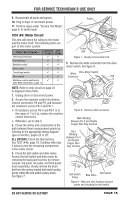
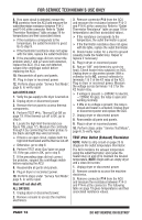
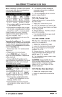
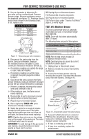
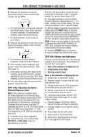
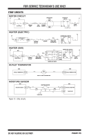
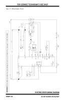
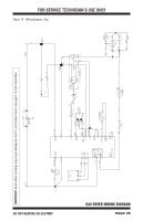
FOR SERVICE TECHNICIAN'S USE ONLY 3. Use an ohmmeter to determine if a gas valve coil has malfunctioned. Remove harness plugs. Measure resistance across the terminals (see figure 11). Readings should match those shown in the following chart; if not, replace coils. 10. Unplug dryer or disconnect power. 11. Reassemble all parts and panels. 12. Plug in dryer or reconnect power. 13. Perform steps under "Service Test Mode", page 6, to verify repair. GAS VALVE RESISTANCE Terminals 1 to 2 1 to 3 4 to 5 Resistance in ohms 1400 ± 70 570 ± 28.5 1300 ± 65 TEST #5: Moisture Sensor This test is performed when an automatic cycle stops too soon, or runs much longer than expected. NOTE: Dryer will shut down automatically after 2½ hours. The following items are part of this system: Black Light Blue White White Light Blue Figure 11 - Measuring gas valve resistance. 4. Disconnect the ignitor plug from the burner. Using an ohmmeter, measure the resistance across the ignitor's 2-pin connector. Resistance should be 50-500 Ω. If resistance readings are outside the range or open, replace the ignitor. If resistance readings are within range, reconnect the ignitor plug and continue to step 5. 5. Disconnect the wires going to the flame sensor terminals. Using an ohmmeter, measure across the two sensor terminals for continuity. If there is continuity, reconnect the sensor wires and continue to step 6. If the reading is open, the flame sensor needs replacing. 6. Reassemble all parts and panels (except toe panel) before reconnecting power. 7. Plug in dryer or reconnect power. 8. Run a high-temp TIMED DRY cycle of at least 2 minutes in duration. 9. Watch the ignitor for a couple of minutes through the front bottom area. If the ignitor stays red hot and the gas does not come out and ignite, the flame sensor needs replacing. NOTE: If ignitor does not come on, line voltage may not be present at the gas burner. The motor centrifugal switch may be suspect. IMPORTANT: To avoid damage to the gas burner wire harness, ensure the harness is routed exactly as it was prior to service. Part of Moisture System Harness/connection Electric Gas Dryer Dryer Metal sensor strips Machine control electronics NOTE: Refer to strip circuit on page 23 to diagnose moisture sensor. NOTE: Overdrying may be caused by a short circuit in the sensor system. 1. Unplug dryer or disconnect power. 2. Remove console to access the machine electronics. 3. Access the moisture sensor wires by removing the toe panel. Disconnect the moisture sensor from the harness. See figure 12. Drum FRONT MOVs (Metal Oxide Varistors) Blower Housing Harness Connection Figure 12 - Disconnect sensor from wire harness. 4. Access the ACU and remove connector P13 from the circuit board. Check the wire harness for continuity between P13 and the moisture sensor connector. If there is continuity, go to step 5. If there is no continuity, replace the main harness. PAGE 20 DO NOT REMOVE OR DESTROY
-
 1
1 -
2
-
3
-
4
-
5
-
6
-
7
-
8
-
9
-
10
-
11
-
12
-
13
-
14
-
 15
15 -
 16
16 -
 17
17 -
 18
18 -
 19
19 -
 20
20 -
 21
21 -
 22
22 -
 23
23 -
 24
24 -
 25
25 -
26
-
27
-
28
-
29
-
30
-
31
-
32
-
33
-
34
-
35
-
36
-
37
-
38
-
39
-
40
-
41
-
42
-
43
-
44
-
45
-
46
-
47
-
48
-
49
-
50
-
51
-
52
-
53
-
54
-
55
-
56
 |
 |
